


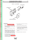
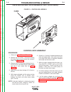
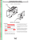

GAS SOLENOID
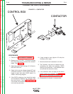
CONTROL BOX
CONTROL BOX COVER
" .+V ,,(%'("
,,(%'("-,-(CONTINUED)
)+(.+
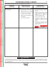
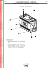
1. Perform the Case Removal Procedure.
2. Remove the five #10-24 x .50 screws holding
the control box cover and access the solenoid
leads. See <:HE8.
3. Apply the correct input voltage (15-110vdc) to
the unit.
4. While pressing the gas purge button or acti-
vating the gun trigger, check for approximate-
ly 4VDC is present at the solenoid leads. If
the 4VDC is present the solenoid should acti-
vate. If the 8VDC is present but the solenoid
does not activate the solenoid may be faulty.
5. If the 4VDC is missing or low, check the leads
and connections between the solenoid and
the control board. See the Wiring Diagram.
If the leads and connections are ok, the con-
trol board may be faulty.
6. If high voltage is seen (Approx. 35 volts) the
solenoid coil is open.
7. Normal solenoid coil resistance is 22 ohms.
8. The solenoid can also be checked by discon-
necting the leads and applying 12VDC direct-
ly to the terminals. If the solenoid does not
activate the solenoid is faulty.
9. If the solenoid fails any of the above tests
replace it.
10. Reassemble the feeder in reverse order.
-+(.%,!((-"' +)"+
%'S)+(
Return to Section TOC Return to Section TOC Return to Section TOC Return to Section TOC
Return to Master TOC Return to Master TOC Return to Master TOC Return to Master TOC