


(.-).-)+(%&,
Observe Safety Guidelines detailed in the beginning of this manual.
)+(%&,
,2&)-(&,
)(,,"%+,(
&",#.,-&'-,
+(&&'
(.+,(-"('
If for any reason you do not understand the test procedures or are unable to perform the tests/repairs safely,
contact the Lincoln Electric Service Department for technical troubleshooting assistance before you proceed.
Call 1-888-935-3877.
.-"('
-+(.%,!((-"' +)"+
%'S)+(
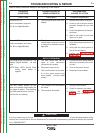
Inconsistent wire feeding or wire not
feeding but the drive rolls are turn-
ing.
1. The gun cable is kinked.
2. The wire is jammed in the gun
cable.
3. The gun liner is dirty or worn.
4. The electrode is rusty or dirty.
5. The gun tip is worn or has splat-
ter.
6. Improper gun liner, tip, drive
rolls, or wire guides.
7. Incorrect pressure on the wire
drive rolls.
8. Spindle brake to tight.
9. Worn drive rolls.
1. Keep the gun as straight as
possible. Avoid sharp corners
or bends in the gun cable.
2. Remove the gun and clear the
jam.
3. Clear liner with pressurized air
(40 PSI) or less. Change liner if
worn.
4. Use only clean electrode. Use
only quality electrode, like L-50
or L-56 from the Lincoln
Electric.
5. Replace the contact tip.
6. Verify the proper parts are
installed.
7. Adjust the tension arm per the
manual. Most electrodes feed
well with the tension at around
“3”.
8. Verify the spool moves with
minimal effort.
9. Replace the drive rolls if need-
ed.
Wire feed speed consistently oper-
ates at the wrong value. The speed
changes when the control knob is
adjusted.
1. The jumper lead for normal
speed / extra torque is connect-
ed improperly.
2. The wrong gear is installed in
the wire drive unit.
3. The motor brushes are worn.
1. Properly connect the jumper.
2. Install the proper pinion fear in
the wire drive unit.
3. Replace the motor/gearbox
assembly.
This wire feeds but cannot be con-
trolled with the wire speed pot.
1. The tachometer is connected
improperly.
2. The tachometer has failed.
1. Verify that tachometer leads
are properly connected.
2. Perform the MOTOR AND
TACHOMETER TEST. Replace
the tachometer if necessary.
3. Possible control board problem.
Return to Section TOC Return to Section TOC Return to Section TOC Return to Section TOC
Return to Master TOC Return to Master TOC Return to Master TOC Return to Master TOC