


()+-"('
%'S)+(
,+('-('-+(%, ,88<:HE8
'%( /(%-&-+
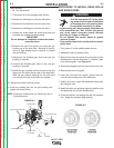
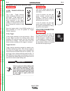
The analog voltmeter shows the voltage between
electrode and work. The voltmeter shows open cir-
cuit voltage when the wire feeder is not welding. As
a result, it is not unusual to see the needle “pegged”
when not welding. The voltmeter is polarity insensi-
tive and the range is 0 - 40VDC.
0"+,)$'(
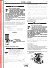
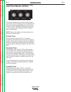
The large, calibrated wire feed speed knob makes
for easy and accurate adjustment of the wire feed
speed. The knob rotates 3/4 turn. Turn the knob
clockwise to increase the wire feed speed, and
counter clockwise to reduce the wire feed speed.
Models with analog voltmeters have a calibrated
scale printed around the wire feed speed knob using
"in/min" units. A separate decal with "m/min" units is
included with these models wire feeder. Units with a
range switch have two calibrated scales.
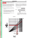
0<E8887,C887/(C8E4G<BA
When Across the Arc models are operated with CV
power sources, the wire feed speed will remain a con-
stant value, independent of arc voltage changes, as
long as the arc voltage does not drop below the mini-
mum values per the following table.
-%/()+-"('
1
1
2
3
2
3
4
4
5
5
6
6
7
K2613-1 & K2613-2
K2613-5 & K2613-7
" .+
"-&
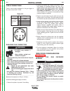
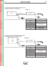
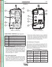
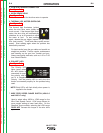
,+")-"('
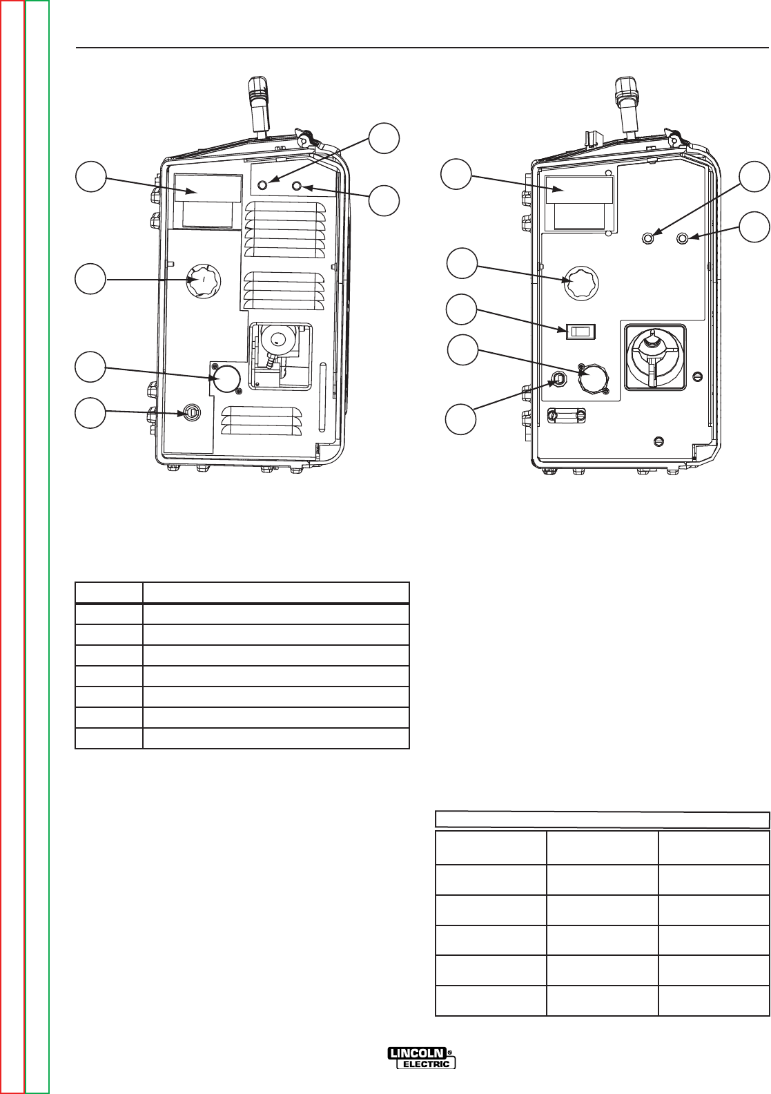
1. Analog Voltmeter
2. Wire Feed Speed Control
3. 5-Pin Gun Trigger Receptacle
4. Work Sense Lead Connector
5 Thermal LED (Motor Overload)
6. Polarity LED
7. Wire Feed Speed Range Switch
&<A<@H@
E6/B?G4:8
&4K<@H@0,
,G4A74E7
&4K<@H@0,
KGE4-BEDH8
15 V 280”/min. 210”/min.
17V 340”/min. 235”/min.
21V 440”/min. 400”/min.
24V 520”/min. 400”/min.
27V 600”/min 400”/min.
Return to Section TOC Return to Section TOC Return to Section TOC Return to Section TOC
Return to Master TOC Return to Master TOC Return to Master TOC Return to Master TOC