


&"'-''
%'S)+(
%-+",!($64A><??
R B ABG BC8E4G8 J<G; 6BI8EF
E8@BI87
R -HEA B99 CBJ8E FBHE68 589BE8
<AFG4??<A:BEF8EI<6<A:
R B ABG GBH6; 8?86GE<64??L ;BG
C4EGF
R-HEA G;8 <ACHG CBJ8E GB G;8 J8?7<A: CBJ8E
FBHE68B994GG;89HF85BK589BE8JBE><A:<AG;8
G8E@<A4?FGE<C
R(A?L DH4?<9<87 C8EFBAA8? F;BH?7<AFG4??HF8BE
F8EI<68G;<F8DH<C@8AG
0+'"'
,-2)+.-"(',
+(.-"'&"'-''
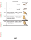
• Check weld cables and gas hoses for cuts.
• Clean and tighten all weld terminals.
)+"("&"'-''
• Clean drive rolls and inner wire guide and replace if
worn.
• Blow out or vacuum the inside of the feeder.
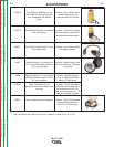
%"+-"(',)""-"('
The voltmeter and flow meter are not calibrated and
are for reference purposes only.
/B?G@8G8E/4?<74G<BA6EBFFG;8E6A4?B:&8G8E
&B78?F
Tools required:
• DC voltmeter reference standard
• Constant voltage DC welding power source with
adjustable no-load voltage (DC-400, V-350, CV-400
or equivalent).
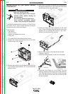
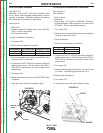
To verify the analog voltmeter accuracy:
1. Turn power OFF.
2. Connect the LN-25™ PRO to the constant voltage
DC welding power source. The work lead of the
LN-25™ PRO must be connected to the work ter-
minal of the power source.
3. Connect the reference voltmeter between the brass
block of the LN-25™ PRO and the work lead.
4. Turn power ON.
5. Energize the output circuit of the power source.
Adjust the power source output to 20±1 VDC as
measured on the reference meter.
6. Verify that LN-25™ PRO voltmeter reads between
19 and 21 volts.
If the voltmeter reading is out of range, check for loose
connections or replace the voltmeter. There is no cal-
ibration adjustment for the LN-25™ PRO voltmeter.
?BJ&8G8E/4?<74G<BA
-BB?FE8DH<E87
• Flow meter reference standard.
• Constant voltage DC welding power source (DC-
400, V-350, CV-400 or equivalent).
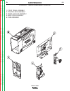
To verify the flow meter accuracy:
1. Turn power OFF.
2. Connect the LN-25™ PRO to the constant voltage
DC welding power source. The work lead of the
LN-25™ PRO must be connected to the work ter-
minal of the power source.
3. Connect a supply of CO2 to the wire feeder. Do not
exceed the maximum inlet pressure of the wire
feeder.
4. Disconnect the shielding gas hose that connects to
the gun bushing.
5. Connect the shielding gas hose to flow meter refer-
ence standard.
6. Orient the LN-25™ PRO in a vertical position.
7. Turn power ON.
8. Adjust the flow meter on the LN-25™ PRO to 40
scfh while pressing the GAS PURGE button.
9. Measure the gas flow with the calibrated flow meter
while pressing the GAS PURGE button.
10. The measured flow rate should be between 35
and 45 scfh.
The LN-25™ PRO flow meter cannot be calibrated. If
the flow meter reads incorrectly, check for leaks or
ki
nks in the gas hose. Replace the flow meter if neces-
sary.
Return to Section TOC Return to Section TOC Return to Section TOC Return to Section TOC
Return to Master TOC Return to Master TOC Return to Master TOC Return to Master TOC