


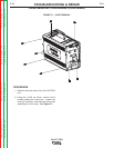


CASE
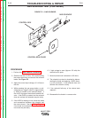
CONTROL BOX ASSEMBLY
" .+V('-+(%(1,,&%2
&(-(+(/+%(-,-(CONTINUED)
)+(.+
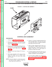
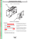
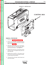
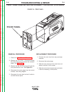
1. Perform the Case Removal Procedure.
2. Remove the 5 #10-24 x .50 screws holding
the control box cover to access the contactor
leads. See Figure F.2.
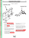
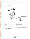
3. Remove the five #10-24 screws holding the
control box cover, and locate the two motor
leads and 3 tach leads. See the Wiring
Diagram.
4. Apply the correct input voltage (15-110vdc) to
the unit.
5. With the trigger activated and the motor run-
ning check the motor armature current.
Normal armature current is less then 3 amps.
6. If the amperage exceeds 3.2 amps for more
than 8 seconds the motor will be disabled.
7. If the motor armature current is normal and
the motor still shuts down the control board
may be faulty.
8. If the current is high check for restrictions in
the feed system. They can be caused by a
clogged liner, spindle tightness, drive rolls to
tight, fault drive motor or a faulty gearbox.
9. After testing replace faulty parts and reassem-
ble the feeder in reverse order of disassembly.
-+(.%,!((-"' +)"+
%'S)+(
Return to Section TOC Return to Section TOC Return to Section TOC Return to Section TOC
Return to Master TOC Return to Master TOC Return to Master TOC Return to Master TOC