


()+-"('
%'S)+(
,).+ ).,!.--('
The gas solenoid valve will energize but neither the
power source output nor the drive motor will be turned
on. The Gas Purge switch is useful for setting the
proper flow rate of shielding gas and for purging the
lines.. Flow meters should always be adjusted while
the shielding gas is flowing.
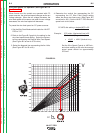
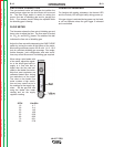
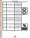
%(0&-+
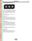
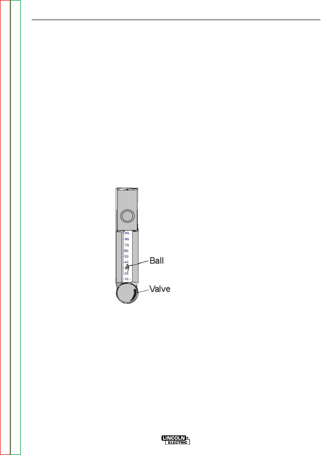
The flowmeter shows the flow rate of shielding gas and
has a valve to adjust the flow. The flow meter is scaled
for CO
2
, Ar, and Ar/CO
2
blends. The middle of the ball
indicates the flow rate of shielding gas.
Adjust the flow rate while depressing the GAS PURGE
switch by turning the valve at the bottom of the meter.
Most weld procedures require 25-40 scfh (11.8 - 18.9
lpm) for sufficient shielding gas coverage. Gun angle,
nozzle diameter, joint configuration and wind condi-
tions may effect the amount of shielding gas required.
When using a wire feeder with
a flow meter, adjust the regula-
tor at the shield gas bottle or
supply to a flow rate that is
higher than the flow rate indi-
cated on the feeder flow meter.
Note that most regulators are
calibrated based upon having
low restrictions on the outlet.
The valve on the feeder flow
meter creates a high restric-
tion and may cause errors in
the readings at the supply reg-
ulator. Set the gas flow rate
using the feeder flow meter
reading and not the supply
regulator reading.
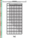
,! %<G8E&<A
10 4.7
20 9.4
30 14.2
40 18.9
50 23.6
60 28.3
70 33.1
80 37.8
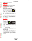
)(0+.),*.'
For feeders with analog voltmeters, the thermal LED
and the Polarity LED will light breifly during power-up.
If the gun trigger is activated during power up, the feed-
er will not operate unless the gun trigger is released
and re-activated.
Return to Section TOC Return to Section TOC Return to Section TOC Return to Section TOC
Return to Master TOC Return to Master TOC Return to Master TOC Return to Master TOC