


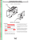
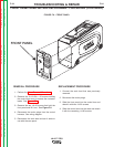
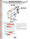

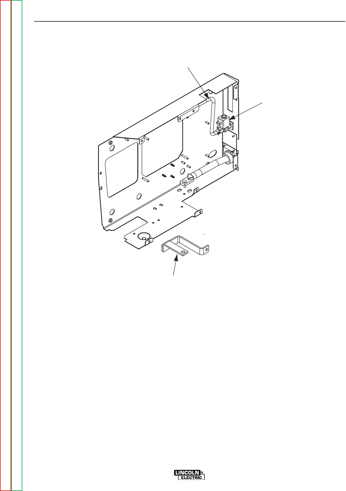
Gas SolenoidGas Solenoid
Gas HoseGas Hose
Buss BarBuss Bar
" .+V.,,+' ,!(,+&(/%
0"++"/&(-(+' +(1
+&(/%'+)%&'-)+(.+(CONTINUED)
+&(/%)+(.+
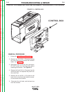
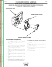
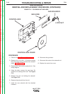
1. Perform the Case Removal Procedure.
2. Remove the 5 #10-24 x .50 screws holding
the control box cover to access the contactor
leads. See Figure F.2.
3. Disconnect the gas hose and the buss bar
from the drive deck. See <:HE8.
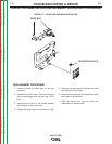
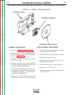
4. Remove the four #10-24 x .50 screws holding
the control box cover.
5. Remove the five #10-24 x .50 screws from the
wire drive panel, and separate the panel from
the control box. See Figure F.10.
6. Remove the plastic drive gear cover and with
a phillips head screwdriver remove the drive
gear. See Figure F.10.
7. Remove the tach and motor leads by discon-
necting the P9 connector. see wiring diagram.
8. Remove the three M6 x 1.00 phillips pan head
screws holding the motor to the motor panel
and lift out the motor.
9. Remove the four 1/4-20 x .50 screws from the
back of the motor panel and remove the drive
deck. Note screw locations for reassembly.
-+(.%,!((-"' +)"+
%'S)+(
Return to Section TOC Return to Section TOC Return to Section TOC Return to Section TOC
Return to Master TOC Return to Master TOC Return to Master TOC Return to Master TOC