


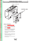

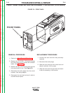


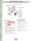

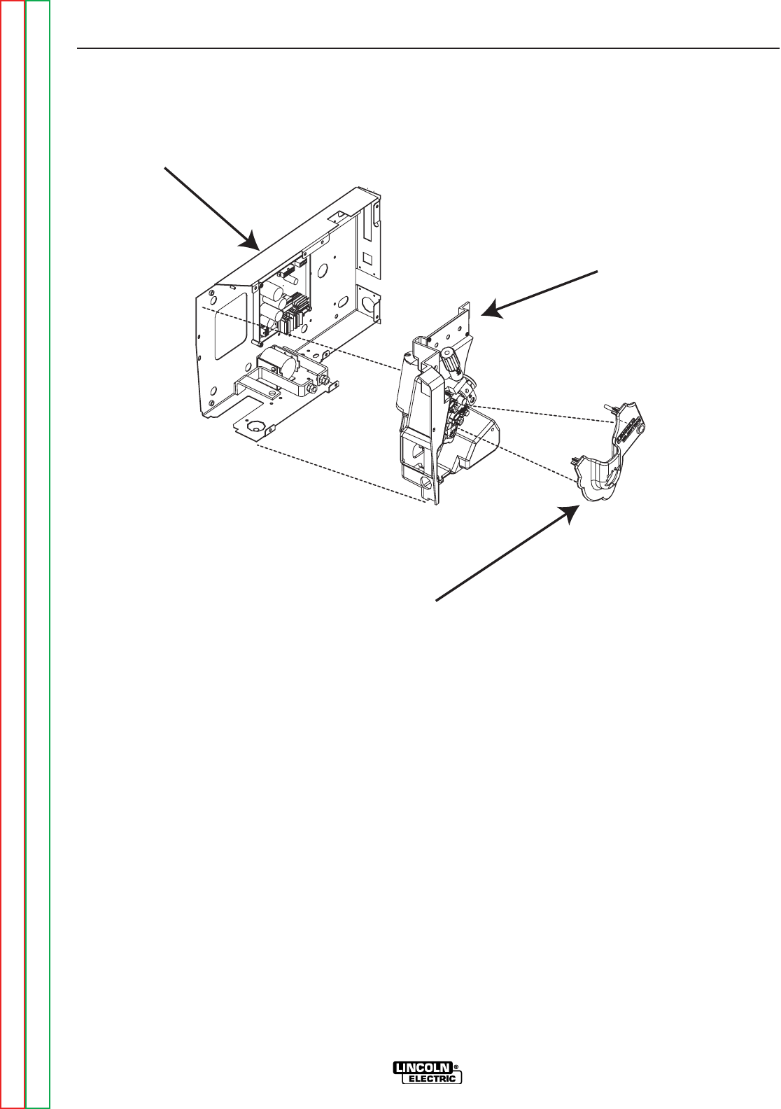
CONTROL BOX
WIRE DRIVE PANEL
DRIVE GEAR COVER
" .+V0"++"/)'%+&(/%
0"++"/&(-(+' +(1
+&(/%'+)%&'-)+(.+(CONTINUED)
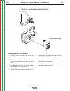
+)%&'-)+(.+
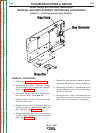
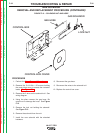
1. Line up the gear box with the four holes on the
panel. Replace and tighten the four 1/4-20 x
.50 screws.
2. Insert the drive motor through the panel and
gear box. Line up and tighten the three M6 x
1.00 in. phillips pan head screws.
3. Replace the drive gear and secure in place
using the screw and lock washer previously
removed.
4. Replace the drive rolls and secure the locking
rings.
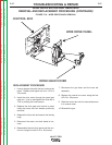
5. Reconnect the motor and tach leads to har-
ness.
6. Reassemble the wire drive panel and the con-
trol box using the five #10-24 x .50 screws.
7. Reconnect the gas hose and the buss bar
assembly.
8. Replace the control box cover using the four
#10-24 x .50 screws.
9. Slide the control box into the case and secure
it in reverse order.
10. Reinstall the gun.
-+(.%,!((-"' +)"+
%'S)+(
Return to Section TOC Return to Section TOC Return to Section TOC Return to Section TOC
Return to Master TOC Return to Master TOC Return to Master TOC Return to Master TOC