


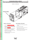
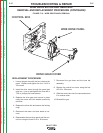

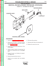

CONTROL BOX COVER
CONTROL BOX
CONTROL BOARD
" .+V('-+(%)(+%(-"('
)Z(++&(/%'+)%&'-)+(.+(CONTINUED)
+&(/%)+(.+
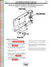
1. Perform the Case Removal Procedure.
2. Remove the 5 #10-24 x .50 screws holding
the control box cover to access the contactor
leads. See Figure F.2.
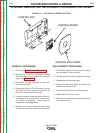
3. Disconnect the gas hose and the buss bar
from the drive deck.
4. Remove the five #10-24 x .50 screws from the
wire drive panel and separate the panel from
the box to access the control board.
5. Locate the control board and remove the har-
ness plugs on the control board. Observe sta-
tic electricity precautions. Label plugs for
reassembly. See <:HE8.
6. Remove the 4 nuts holding the board using
the 3/8 inch nut driver, and remove the board.
+)%&'-)+(.+
1. Remove the new control board from the static
bag and place it on the 4 studs.
2. Reassemble the 4 nuts and tighten hand tight.
3. Reassemble the harness plugs.
4. Replace the wire drive panel and control box
assembly in reverse order.
5. Reconnect the buss bar and the gas hose.
6. Replace the control box cover.
7. Slide the control box into the case and secure
it in reverse order.
-+(.%,!((-"' +)"+
%'S)+(
Return to Section TOC Return to Section TOC Return to Section TOC Return to Section TOC
Return to Master TOC Return to Master TOC Return to Master TOC Return to Master TOC