


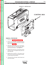
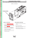


FRONT PANEL
" .+V+('-)'%
+('-)'%+&(/%'+)%&'-)+(.+(CONTINUED)
+&(/%)+(.+
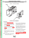
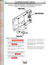
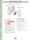
1. Perform the Case Removal Procedure.
2. Remove the 5 #10-24 x .50 screws holding
the control box cover to access the contactor
leads. See Figure F.2.
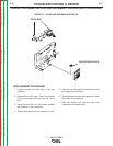
3. Remove the two 1/4-20 screws that hold the
front panel and lift it out. See <:HE8
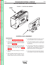
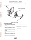
4. Disconnect the molex plugs from the control
harness. See wiring diagram.
5. Disconnect the work lead and set it aside to
use with the new panel.
+)%&'-)+(.+
1. Connect the work lead that was previously
removed.
2. Reconnect the molex plugs.
3. Slide the front panel into the control box and
attach it with two 1/4-20 screws.
4. Slide the control box into the case and attach
it with the remaining 1/4-20 screws.
-+(.%,!((-"' +)"+
%'S)+(
Return to Section TOC Return to Section TOC Return to Section TOC Return to Section TOC
Return to Master TOC Return to Master TOC Return to Master TOC Return to Master TOC