


-!(+2(()+-"('
%'S)+(
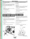
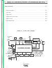
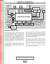
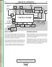
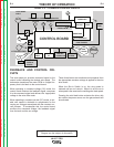
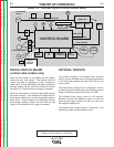
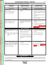
NOTE: Unshaded areas of Block Logic
Diagram are the subject of discussion
$ ' ('-+(% "+
."-,
The wire speed pot provides command signal to the
control board indicating the desired wire speed. The
tachometer transforms the motor RPM to a digital fre-
quency that is fed back to the control board.
When operating in constant voltage (CV) mode, the
control board monitors the feedback signal, compares
it to the command signal and delivers the appropriate
voltage to the wire drive motor.
When operating in constant current (CC) mode, a vari-
able wire speed is desirable to compensate for the
varying arc voltages associated with the constant cur-
rent process. To accomplish this, the control board
monitors the command voltage, the feedback signal
from the tach and the arc voltage.
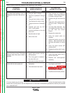
" .+W$('-+(%"+."-,
These three factors are monitored and compared, then
the appropriate armature voltage is applied to the wire
drive motor.
When the Run-in Switch is on, the wire speed is
reduced until an arc is struck. When it is off the run-in
wire speed is the same as the welding wire feed speed.
Pressing the cold feed button activates the drive rolls
but neither the power source nor the gas solenoid will
be activated.
ELECTRODE
INPUT
CONTROL BOARD
FEEDPLATE
MOTOR
TACH
67
CONTACTOR
CURRENT TRANSDUCER
INPUT
SOLENOID
V M
POLARITY
TIMER OPTION
MOTOR
OVERLOAD
21
21
ARMATURE
TACH FEEDBACK
GUN TRIGGER
GUN
RUN IN
DIGITAL
DISPLAY
BOARD
COLD
FEED
CC
CV
TRIGGER
INTERLOCK
GAS
PURGE
WIRE
SPEED
REMOTE
VOLTAGE
14 PIN AMPHENOL
1
Return to Section TOC Return to Section TOC Return to Section TOC Return to Section TOC
Return to Master TOC Return to Master TOC Return to Master TOC Return to Master TOC