


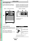
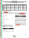
INPUT CONNECTIONS
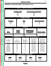
Be sure the voltage, phase, and frequency of the
input power is as specified on the rating plate, lo-
cated on the case front control panel. See Figure
A.1.
Input supply line entry is through a hole in the case
rear top panel. A removable door covers the input
connection box, which contains the input contactor
(CR1) and reconnect panel assembly for multiple volt-
age machines. Input power is connected to the three
line terminals on the input contactor. See Figure A.2.
INSTALLATION
A-4 A-4
LINCOLN
®
ELECTRIC
IDEALARC DC-400
Return to Section TOC Return to Section TOC Return to Section TOC Return to Section TOC
Return to Master TOC Return to Master TOC Return to Master TOC Return to Master TOC
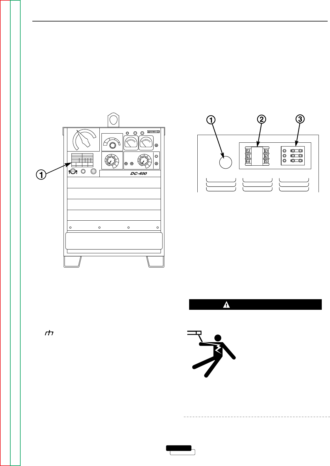
FIGURE A.1 – RATING PLATE LOCATION
FIGURE A.2 – REAR PANEL
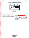
GROUND CONNECTION
The frame of the welder must be grounded. An earth
grounding lead must be connected to the grounding
terminal, marked on the input box floor with the sym-
bol ( ).
INPUT SUPPLY CONNECTIONS
Be sure the voltage, phase, and frequency of the input
power is as specified on the rating plate.
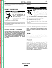
ELECTRIC SHOCK can kill.
• Have a qualified electrician
install and service this equip-
ment.
• Turn the input power off at the
fuse box before working on this
equipment.
• Do not touch electrically hot
parts.
• Insulate yourself from the work and ground.
• Always wear dry insulating gloves.
WARNING
1. RATING PLATE
1. INPUT SUPPLY LINE ENTRY HOLE
2. INPUT CONTACTOR CR1
3. RECONNECT PANEL