


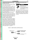
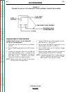
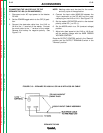
CONNECTING THE LN-8 OR LN-9 TO THE
IDEALARC DC-400 (14-PIN AMPHENOL)
1. Disconnect main AC input power to the Idealarc
DC-400.
2. Set the POWER toggle switch to the OFF (0) posi-
tion.
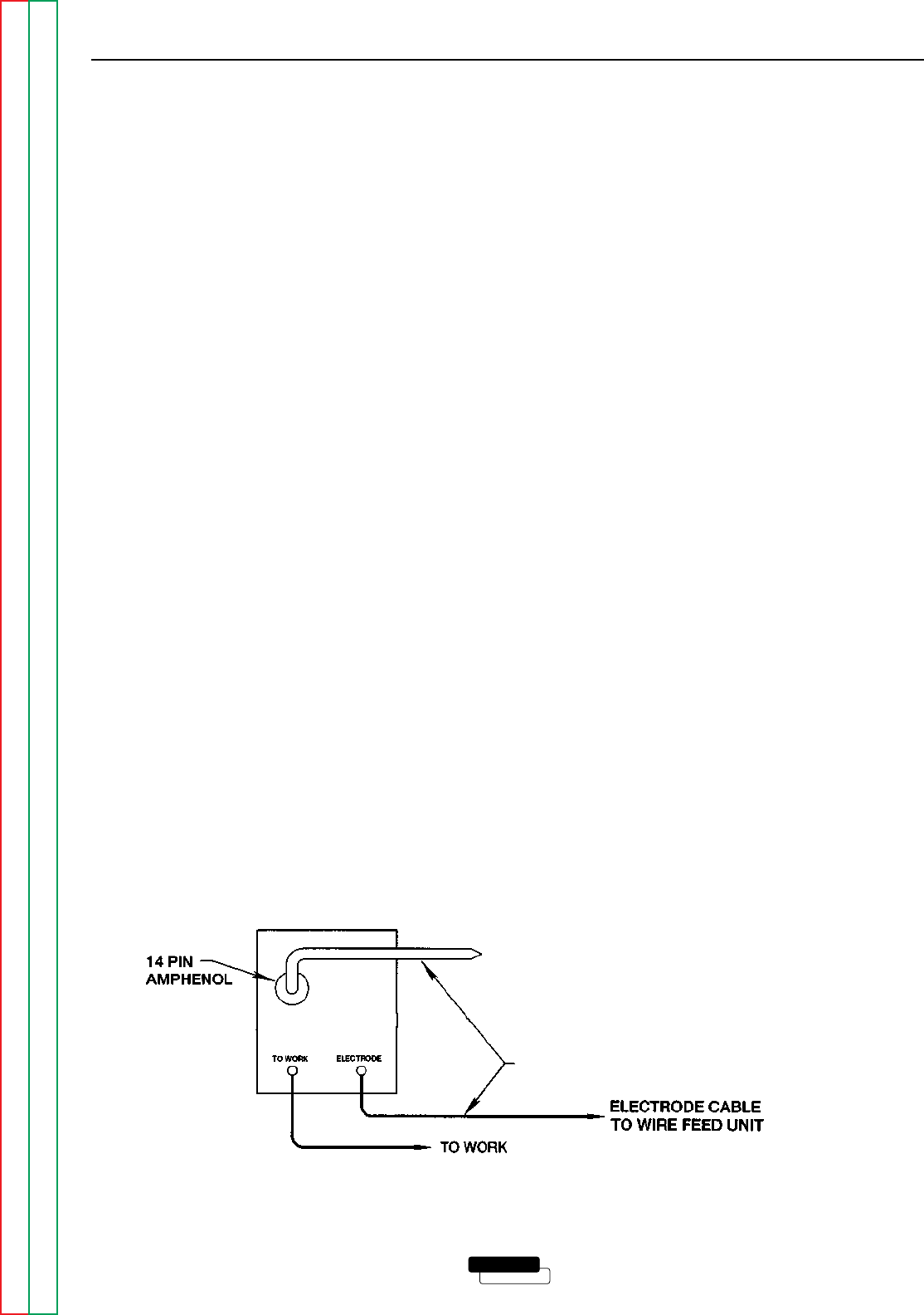
3. Connect the electrode cable from the LN-8 or
LN-9 to the “+” terminal of the welder. Connect
the work cable to the “-” terminal of the welder.
Reverse this hookup for negative polarity. See
Figure C.10.
NOTE: Welding cable must be sized for the current
and duty cycle of the application.
4. Connect the input cable (K595-XX) between the
14-pin amphenol on the DC-400 and the input
cable plug on the LN-8 or LN-9. See Figure C.10.
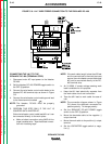
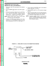
5. Set the welder VOLTMETER switch to the desired
polarity, either DC (-) or DC (+).
6. Set the MODE switch to a CV (constant voltage)
position.
7. Adjust wire feed speed at the LN-8 or LN-9 and
set the welding voltage with the WIRE FEEDER
VOLTAGE CONTROL.
Place the OUTPUT CONTROL switch in the “Remote”
position and the OUTPUT TERMINALS switch in the
“Remote” position.
ACCESSORIES
C-12 C-12
LINCOLN
®
ELECTRIC
IDEALARC DC-400
Return to Section TOC Return to Section TOC Return to Section TOC Return to Section TOC
Return to Master TOC Return to Master TOC Return to Master TOC Return to Master TOC
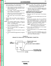
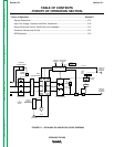
FIGURE C.10 – IDEALARC DC-400/LN-8 OR LN-9 WITH K595-XX CABLE
TO LN8/LN9 INPUT
CABLE PLUG
K595-XX INPUT CABLE ASSEMBLY