


GENERAL DESCRIPTION
The Idealarc DC-400 is an SCR controlled three-phase
input, DC output power source for welding and cut-
ting. It uses a single range potentiometer control. The
welder’s unique combination of transformer, three-
phase semiconverter rectifier, capacitor bank, arc con-
trol choke, and solid state control system deliver out-
standing arc characteristics in the constant voltage
mode. For stick welding, an Arc Force Control enables
the Idealarc-400 to perform much like the R3R-500.
RECOMMENDED PROCESSES
The Idealarc DC-400 is recomended for all open arc
processes including Innershield
®
and all solid wire and
gas procedures within its capacity of 60 to 500 amps.
It also can perform stick and TIG welding and air/car-
bon arc gouging up to 5/16” (8 mm) diameter. A mode
switch on the front control panel selects CV (FCAW,
GMAW), CV Submerged Arc, or CC (stick/TIG).
The Idealarc DC-400 can be connected to wire feed-
ing equipment, including:
• Automatic wire feeders NA-3, NA-5, and NA-5R.
(Requires the DC-400 Diode Kit option to use the
cold start and cold electrode sensing features of
these feeders.)
• Semi-automatic wire feeders LN-7, LN-7 GMA, LN-
8, LN-9, LN-9 GMA, LN23P, LN-25, LN-742.
• Tractors LT-56, LT-7.
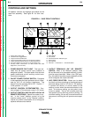
OPERATIONAL FEATURES AND
CONTROLS
The following operational controls are standard on the
Idealarc DC-400:
• Power Source Pilot Light
• ON/OFF Power Toggle Switch
• Output Control Potentiometer
• Output Control Switch (with Local or Remote posi-
tions)
• Output Terminals On or Remote Switch
• Arc Force Selector (for CC stick or TIG processes
only)
• Auxiliary Power Connections for Wire Feeder and
Other Equipment (115V and 42V)
• Mode Switch
• Arc Control
• Thermal Protection Indicator Light
• DC Ammeter
• DC Voltmeter
• Voltmeter “+” Electrode or “-” Electrode Switch
DESIGN FEATURES AND ADVANTAGES
• Input line voltage compensation keeps output con-
stant for fluctuations of ± 10%.
• SCR control extends life of mechanical contactors.
• Hinged front control panel provides easy access to
printed circuit boards and other control circuitry.
• Fully enclosed fan motor with permanently lubri-
cated, sealed ball bearings needs no maintenance.
• Fully recessed control panel protects controls and
minimizes accidental contact.
• Recessed output terminals and hinged terminal
cover reduce chance of accidental contact.
• Low profile case permits installation under a work-
bench.
• Removable rear access panel provides easy access
to input contactor and input lead connections.
• Removable case sides provide easy access for ser-
vice or inspection, even when machines are stacked.
• Dripproof enclosure design permits outdoor operation.
• Double-dipped transformer, SCR bridge, and choke
resist corrosion.
WELDING CAPABILITY
The Idealarc DC-400 has the following duty cycle
ratings. If the duty cycle is exceeded, a thermal pro-
tector will shut off the machine output until it cools to
normal operating temperature. The amber thermal
protection indicator light will turn on until the machine
cools.
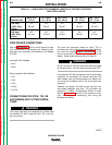
Duty Cycle* Amps Volts
100% 400 36
60% 450 38
50% 500 40
*Based on a 10 minute time period. For example, a 60% duty cycle
means 6 minutes on and 4 minutes off.
LIMITATIONS
The Idealarc DC-400 has no provisions for paralleling.
OPERATION
B-3 B-3
LINCOLN
®
ELECTRIC
IDEALARC DC-400
Return to Section TOC Return to Section TOC Return to Section TOC Return to Section TOC
Return to Master TOC Return to Master TOC Return to Master TOC Return to Master TOC