


5. Extend wire feeder control cable lead #21 so it can
be connected directly to the work piece.
a. Make a bolted connection using AWG #14 or
larger insulated wire. Tape the bolted connec-
tion with insulating tape.
b. An S-16586- X remote voltage sensing work
lead is available for this purpose.
c. Keep the #21 lead electrically separate from
the work cable circuit and connection.
d. Tape the #21 lead to work cable for ease of
use.
6. Connect NA-5 wire feeder control jumpers on
Voltage Control Board. See NA-5 Operator’s
Manual.
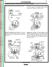
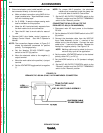
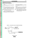
NOTE: The connection diagram shown in Figure C.5
shows the electrode connected for positive
polarity. To change polarity:
a. Set the Idealarc DC-400 POWER toggle
switch to the OFF (0) position.
b. Move the electrode cable to the negative (-)
output terminal.
c. Move the work cable to the positive (+) output
terminal.
d. Set the VOLTMETER toggle switch to negative
(-).
NOTE: For proper NA-5 operation, the electrode
cables must be secured under the clamp bar
on the left side of the NA-5 Control Box.
7. Set the DC-400 OUTPUT CONTROL switch to the
“Remote” position and the OUTPUT TERMINALS
switch to the “Remote” position.
CONNECTING THE NA-3 OR NA-5 TO THE
IDEALARC DC-400 (14-PIN AMPHENOL)
1. Disconnect main AC input power to the Idealarc
DC-400.
2. Set the Idealarc DC-400 POWER switch to the OFF
(0) position.
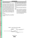
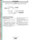
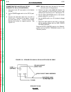
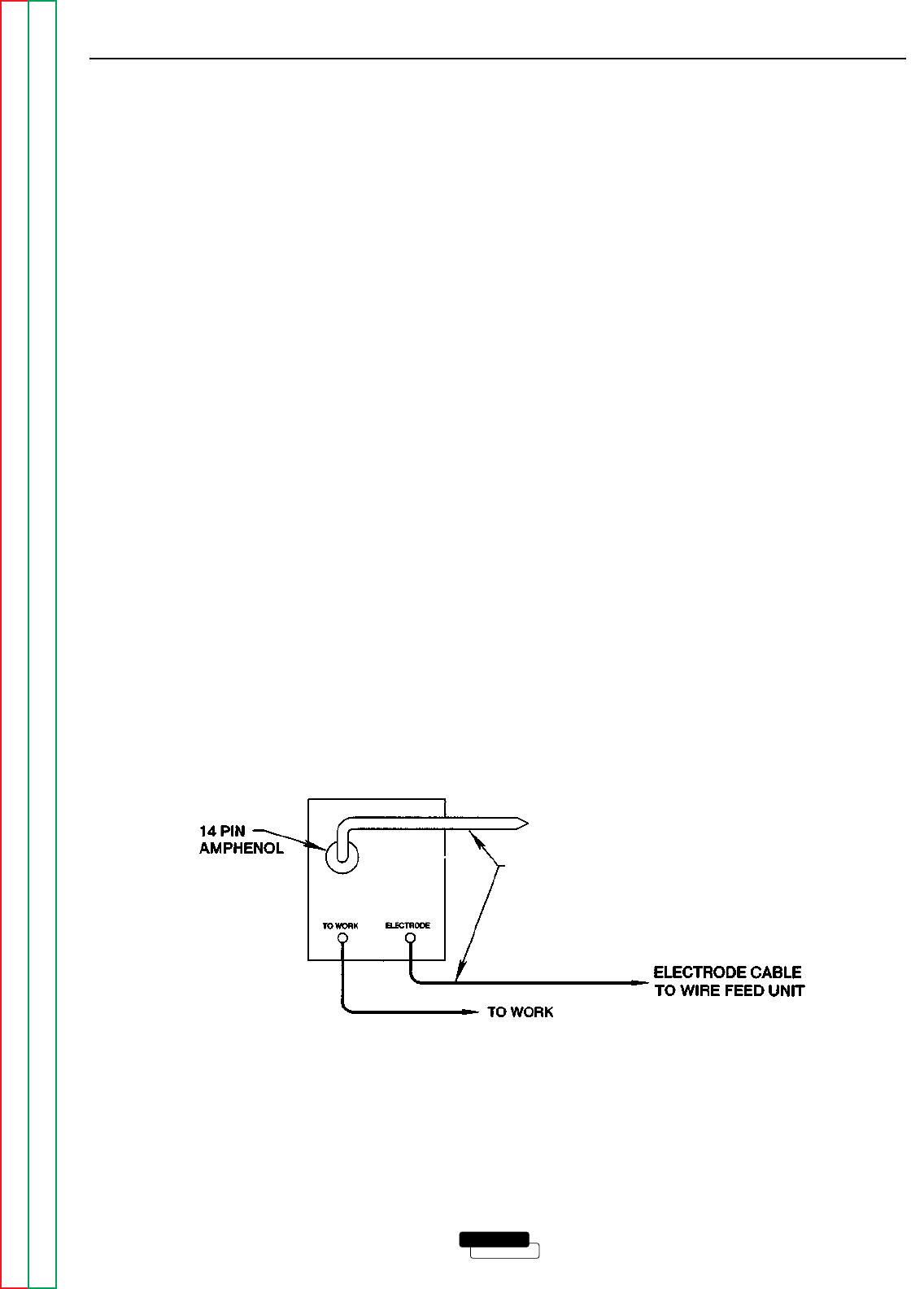
3. Connect the electrode cable from the K597-XX
Input Cable Assembly to the “+” terminal of the
welder and to the wire feeder. Connect the work
cable to the “-” terminal of the welder. Reverse this
hookup for negative polarity. See Figure C.6.
NOTE: Welding cable must be sized for the cur-
rent and duty cycle of the application.
4. Set the welder VOLTMETER switch to the desired
polarity, either DC (-) or DC (+).
5. Set the MODE switch to a CV (constant voltage)
position.
6. Set the DC-400 OUTPUT CONTROL switch to the
“Remote” position and the OUTPUT TERMINALS
switch to the “Remote” position.
ACCESSORIES
C-8 C-8
LINCOLN
®
ELECTRIC
IDEALARC DC-400
Return to Section TOC Return to Section TOC Return to Section TOC Return to Section TOC
Return to Master TOC Return to Master TOC Return to Master TOC Return to Master TOC
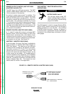
FIGURE C.6
IDEALARC DC-400/NA-3/NA-5 14-PIN AMPHENOL CONNECTION
TO NA-3 or NA-5 INPUT
CABLE PLUG
K597-XX INPUT CABLE ASSEMBLY