


Return to Section TOC Return to Section TOC Return to Section TOC Return to Section TOC
Return to Master TOC Return to Master TOC Return to Master TOC Return to Master TOC
TROUBLESHOOTING & REPAIR
F-56 F-56
LINCOLN
®
ELECTRIC
IDEALARC DC-400
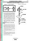
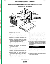
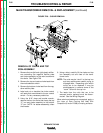
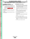
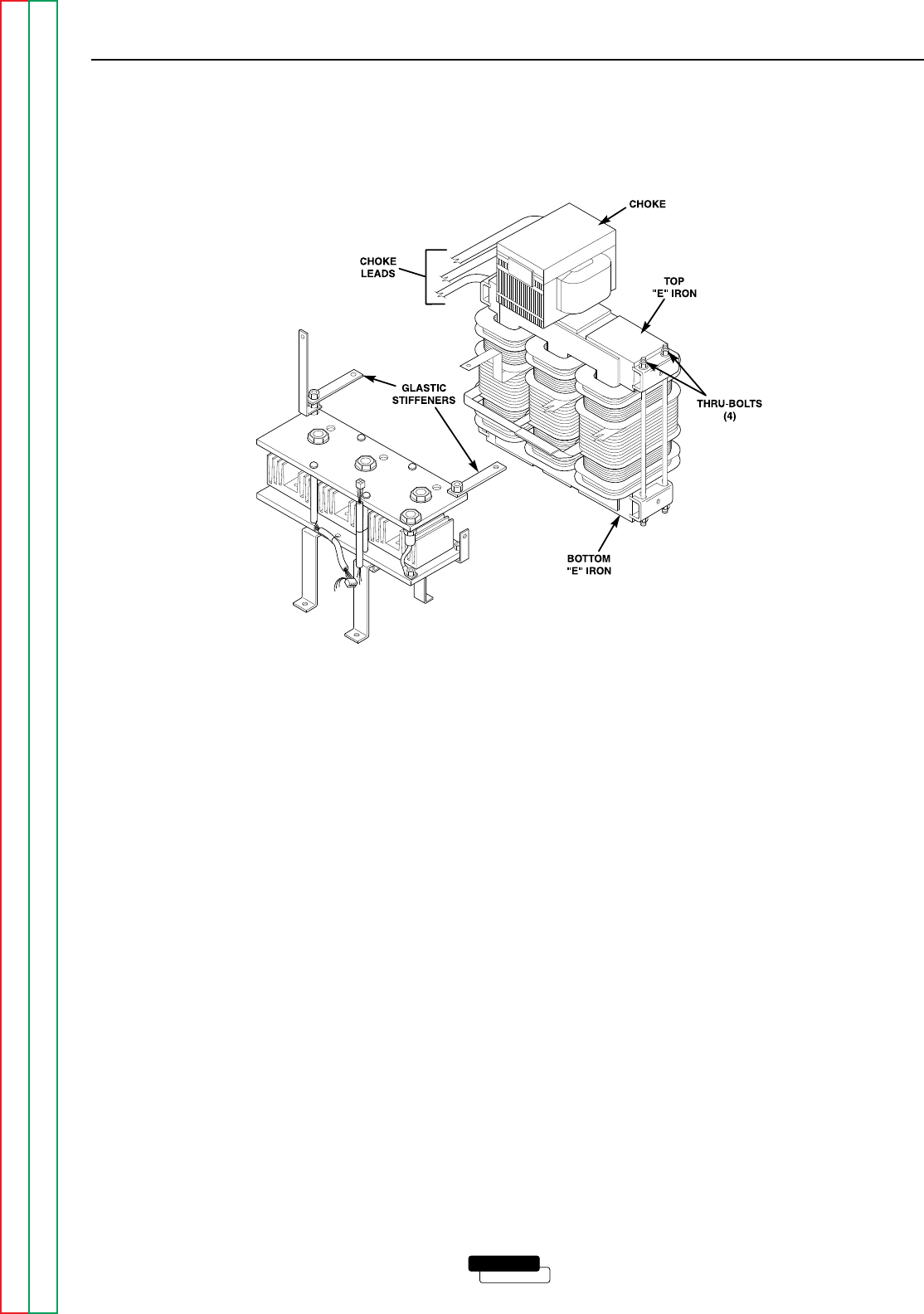
FIGURE F.26 – CHOKE REMOVAL
MAIN TRANSFORMER REMOVAL & REPLACEMENT (continued)
REMOVAL OF CHOKE AND TOP
IRON ASSEMBLY
1. Remove the two (left and right) glastic stiffen-
ers connecting the negative rectifier plate
and choke assembly to the main transformer
thru-bolts. See Figure F.26.
2. Remove the top and center choke leads from
the mode selector switch.
3. Remove the bottom choke lead from the neg-
ative rectifier plate.
4. Label and cut or desolder the choke control
coil leads that are soldered to the arc control
switch. Cut any necessary cable ties.
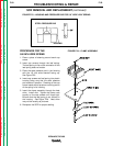
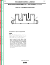
5. Using the 9/16” deep well socket wrench,
remove the four thru-bolts that clamp the top
“E” iron and choke assembly to the bottom
“E” iron. NOTE: for easier reassembly, clean
the threads.
6. Using a hoist, carefully lift the choke and top
iron assembly out and clear of the trans-
former coils.
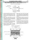
NOTE: The coils may be “stuck” to the top iron
and may require some careful prying to
dislodge them. Depending upon which
coil(s) are to be replaced, it may be
advantageous to remove some of the
“stuck” coils with the top iron.
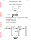
7. The leads from the coils that are to be
removed and/or replaced must be discon-
nected. See the Wiring Diagram.
When aluminum leads are re-connected, apply a
thin layer of Dow Corning 340 Heat Sink
Compound (Lincoln E1868) to mating surfaces.