


Return to Section TOC Return to Section TOC Return to Section TOC Return to Section TOC
Return to Master TOC Return to Master TOC Return to Master TOC Return to Master TOC
TROUBLESHOOTING & REPAIR
F-30 F-30
LINCOLN
®
ELECTRIC
IDEALARC DC-400
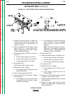
ACTIVE SCR TEST (continued)
TEST PROCEDURE
1. Disconnect the main input supply power to
the machine.
2. With the 5/16” nut driver, remove the case
top and sides. Remove the screws holding
the front panel and lower the panel.
3. Disconnect the welding cables from the
welding output terminals.
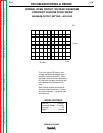
4. Locate and remove molex plugs P1 and P3
from the control board. See Figure F.12.
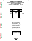
5. Locate and remove molex plug P5 from the
snubber board. See Figure F.13.
6. Rotate the mode switch (S4) to the constant
current (CC) position.
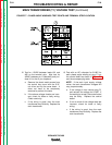
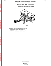
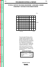
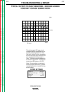
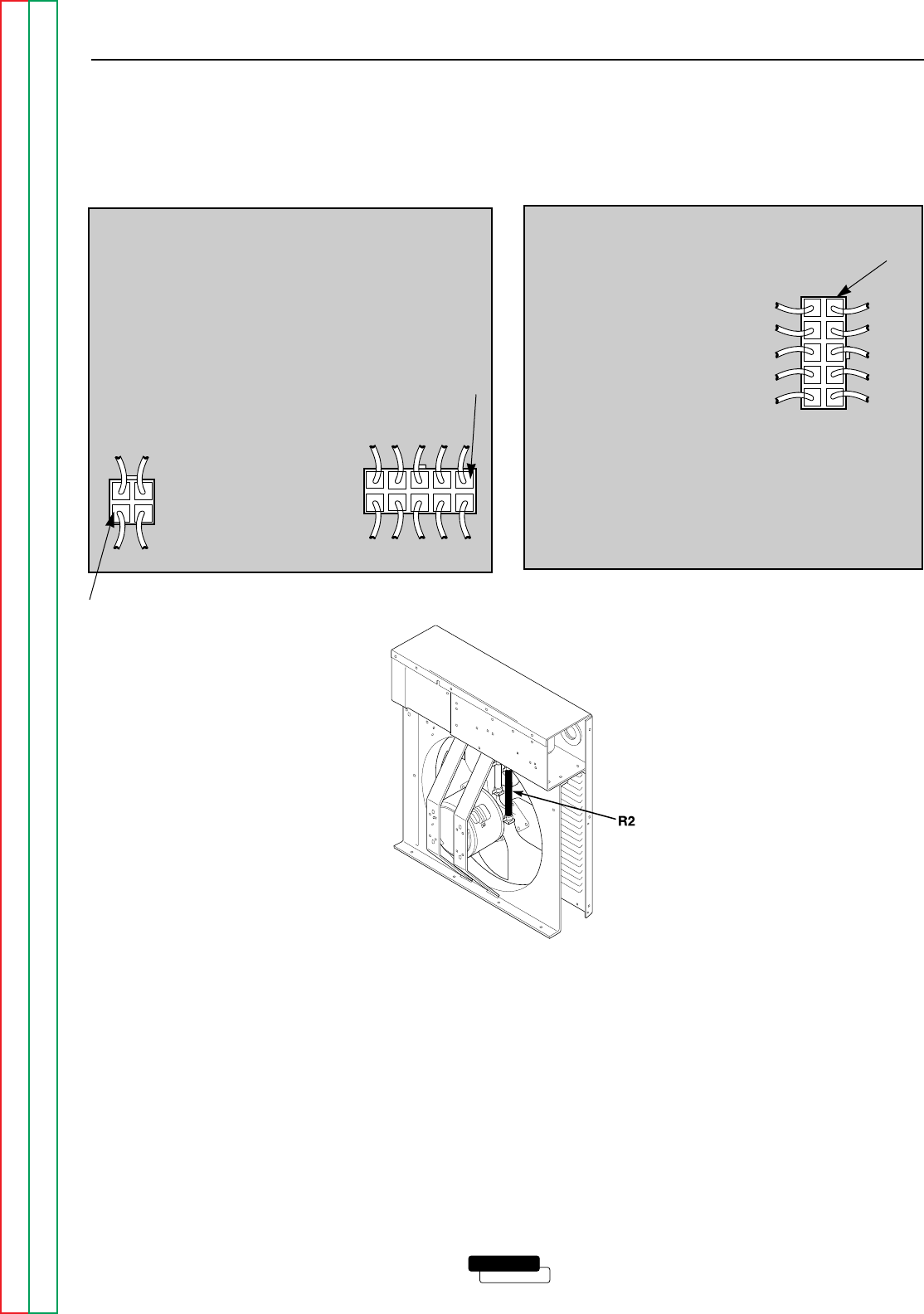
7. Locate and remove lead #204 from resistor
R2 (40 ohms, 50 Watts). See Figure F.14.
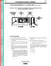
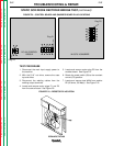
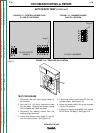
FIGURE F.12 – CONTROL BOARD PLUG
P1 AND P3 LOCATIONS
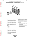
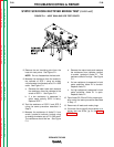
FIGURE F.13 – SNUBBER BOARD
PLUG P5 LOCATION
FIGURE F.14 – RESISTOR R2 LOCATION
DC-400 CONTROL
G2588-X
Plug P1
Plug P3
M15370-X SNUBBER
Plug P5