


G-9
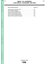
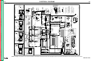
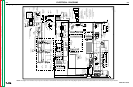
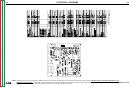
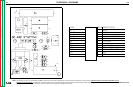
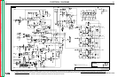
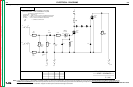
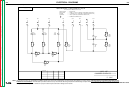
ELECTRICAL DIAGRAMS
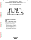
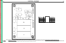
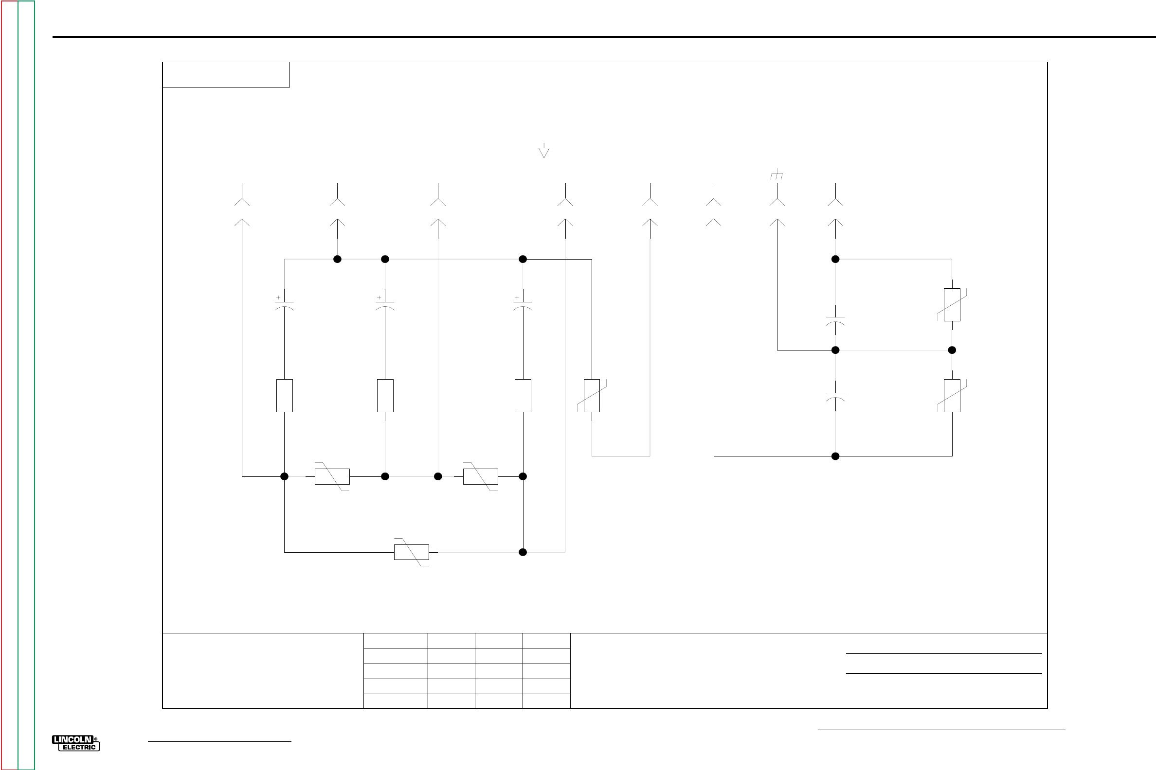
IDEALARC DC400
Snubber PC Board (M15370) Schematic
38J
130V
TP3
S
160J
320V
TP5
19687
225
19687
160J
320V
TP4
600V
.05
C4
600V
.05
C5
J5
8
J5
3
J5
2
J5
4
J5
7
J5
5
SNUBBER SCHEMATIC
J5
1
2W
10
R3
J5
6
80J
150V
TP6
2W
10
R2
2W
10
R1
38J
130V
TP2
ELECTRICAL SYMBOLS PER E1537
GENERAL INFORMATION
CAPACITORS = MFD/VOLTS
RESISTORS = OHMS,1/4 WATT (UNLESS OTHERWISE SPECIFIED)
38J
130V
TP1
.068
400V
C1
1
2
.068
400V
C2
1
2
DIODES = 1 AMP/400 VOLT (UNLESS OTHERWISE SPECIFIED)
OP AMPS = LM124 (UNLESS OTHERWISE SPECIFIED)
=
COMMON CONNECTION
224220
223204 222221
S
.068
400V
C3
1
2
MISC. USE
3-8-91G
G-9
Return to Section TOC Return to Section TOC Return to Section TOC Return to Section TOC
Return to Master TOC Return to Master TOC Return to Master TOC Return to Master TOC
NOTE: Lincoln Electric assumes no responsibility for liablilities resulting from board level troubleshooting. PC Board repairs will invalidate your factory warranty. Individual Printed Circuit Board Components are not
available from Lincoln Electric. This information is provided for reference only. Lincoln Electric discourages board level troubleshooting and repair since it may compromise the quality of the design and may result
in danger to the Machine Operator or Technician. Improper PC board repairs could result in damage to the machine.