


Have a qualified electrician connect the input power
leads to the L1, L2, and L3 terminals of the input con-
tactor. Follow all national and local electrical codes.
Use a three-phase line. Refer to the connection dia-
gram located on the inside cover of the access panel
cover. Also see Figure A.3.
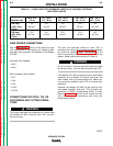
INPUT WIRE AND FUSE SIZE
Fuse the input circuit with the super lag fuses recom-
mended on the Technical Specifications page or use
delay type circuit breakers. Choose an input and
grounding wire size according to local or national
codes; also see the Technical Specifications page.
Using fuses or circuit breakers smaller than recom-
mended may result in “nuisance” shut-offs from
welder inrush currents, even if you are not welding at
high currents.
INSTALLATION
A-5 A-5
LINCOLN
®
ELECTRIC
IDEALARC DC-400
Return to Section TOC Return to Section TOC Return to Section TOC Return to Section TOC
Return to Master TOC Return to Master TOC Return to Master TOC Return to Master TOC
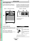
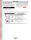
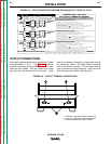
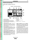
FIGURE A.3 – INPUT POWER SUPPLY CONNECTIONS
1. INPUT SUPPLY LINE
2. INPUT CONTACTOR CR1
3. RECONNECT PANEL