


Return to Section TOC Return to Section TOC Return to Section TOC Return to Section TOC
Return to Master TOC Return to Master TOC Return to Master TOC Return to Master TOC
TROUBLESHOOTING & REPAIR
F-37 F-37
LINCOLN
®
ELECTRIC
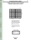
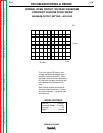
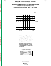
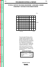
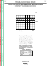
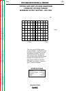
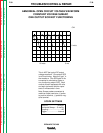
IDEALARC DC-400
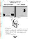
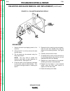
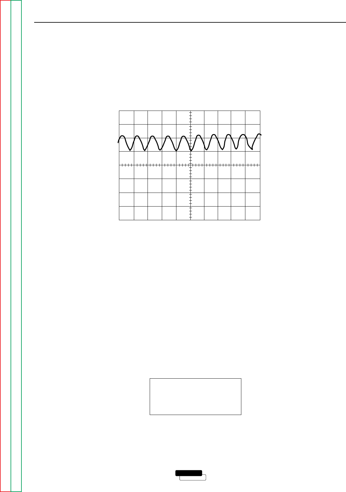
This is the typical DC open circuit
voltage waveform generated from a
properly operating machine. Note
that each vertical division represents
20 volts and that each horizontal divi-
sion represents 5 milliseconds in
time. The machine was loaded with
a resistance grid bank. The DC-400
meters read 400 amps at 36 VDC.
Note: Scope probes connected at
machine output terminals: (+) probe
to positive terminal, (-) probe to neg-
ative terminal.
SCOPE SETTINGS
Volts/Div.....................20V/Div.
Horizontal Sweep.....5 ms/Div.
Coupling ............................DC
Trigger .........................Internal
TYPICAL OUTPUT VOLTAGE WAVEFORM – MACHINE LOADED
CONSTANT VOLTAGE SUBARC MODE
CH1
0 volts
5 ms
20 volts