


NA-3 AUTOMATIC WIRE FEEDER
1. Set the DC-400 OUTPUT CONTROL switch to
“Remote.”
NOTE: Later model NA-3 automatic wire feeders
are capable of cold starts when the NA-3
Mode switch is in the CV or CC mode posi-
tion. Some earlier models are capable of
cold starting only in the CC mode position.
Cold starting enables you to inch the wire
down to the work, automatically stop, and
automatically energize the flux hopper
valve. The cold start feature requires the
factory installed diode option. See the
Accessories section.
2. Set the DC-400 welding MODE switch for the
desired process: CV Submerged Arc, CV
FCAW/GMAW mode or CC mode.
3. Set the NA-3 mode switch position to either CV or
CC to match the DC-400 mode selected in step 2.
4. Set the OUTPUT CONTROL switch to “Remote.”
5. Set the OUTPUT TERMINALS switch to “Remote.”
6. For CC welding, set the ARC FORCE CONTROL to
midrange, 5-6. After welding starts, adjust as nec-
essary.
7. For CV FCAW/GMAW welding, set the ARC CON-
TROL to midrange, 3. After welding starts, adjust
as necessary.
8. Refer to the NA-3 operator’s manual for instructions
on how to use the NA-3 in conjunction with the DC-
400.
9. Follow the guidelines for good arc striking detailed
below for each welding mode.
GOOD ARC STRIKING GUIDELINES FOR THE
NA-3 WITH THE IDEALARC DC-400 IN THE CV
FCAW/GMAW, CV SUBMERGED ARC OR
STICK/TIG CC WELDING MODES.
Following are some basic arc striking techniques that
apply to all wire feed processes. Using these proce-
dures should provide trouble-free starting. These pro-
cedures apply to single, solid wires and Innershield
wires.
1. Cut the electrode to a sharp point.
2. Set the NA-3 Open Circuit Voltage Control to the
same dial setting as the Arc Voltage Control. If this
is a new welding procedure, a good starting point is
to set the Open Circuit Voltage Control to #6.
NOTE: The open circuit voltage of the Idealarc
DC-400 varies from apporximately 12
volts to 45 volts in the CV FCAW/GMAW
or CV Submerged Arc modes. The open
circuit voltage is constant in the CC mode.
3. Run a test weld. Set proper current, voltage, and
travel speed.
a. For the best starting performance, the NA-3
Open Circuit Voltage Control and Voltage
Control setting should be the same. Set the
Inch Speed Control for the slowest inch speed
possible.
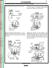
b. To adjust the Open Circuit Voltage Control to
get the best starting performance, make
repeated starts observing the NA-3 voltmeter.
When the voltmeter pointer swings smoothly up to
the desired arc voltage, without undershooting or
overshooting the desired arc voltage, the Open
Circuit Voltage Control is set properly.
If the voltmeter pointer overshoots the desired
voltage and then returns to the desired voltage, the
Open Circuit Voltage Control is set too high. This
can result in a bad start where the wire tends to
“blast off.”
If the voltmeter pointer hesitates before coming up
to the desired voltage, the Open Circuit Voltage
Control is set too low. This can cause the elec-
trode to stub.
4. Start and make the weld.
a. Cold starts. For cold starts, be sure the work
piece is clean and the electrode makes posi-
tive contact with the work piece.
b. Hot “On the Fly” starts. For hot starts, travel
should begin before the wire contacts the work
piece.
ARC STRIKING WITH THE NA-3 START BOARD
When electrical stickouts exceed 1-3/4” (44.4 mm) an
NA-3 Start Board may be required to improve arc strik-
ing.
When the NA-3 Start Board is used to improve arc
striking, use the following procedures:
1. Set start time at 0.
2. Set NA-3 start current and start voltage at mid-
range.
3. Set the NA-3 output current and voltage to the
proper settings for the welding procedure to be
used.
OPERATION
B-7 B-7
LINCOLN
®
ELECTRIC
IDEALARC DC-400
Return to Section TOC Return to Section TOC Return to Section TOC Return to Section TOC
Return to Master TOC Return to Master TOC Return to Master TOC Return to Master TOC