


Return to Section TOC Return to Section TOC Return to Section TOC Return to Section TOC
Return to Master TOC Return to Master TOC Return to Master TOC Return to Master TOC
TROUBLESHOOTING & REPAIR
F-45 F-45
LINCOLN
®
ELECTRIC
IDEALARC DC-400
SCR/DIODE RECTIFICER ASSEMBLY
REMOVAL AND REPLACEMENT (continued)
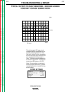
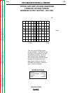
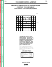
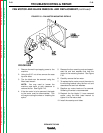
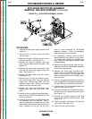
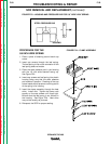
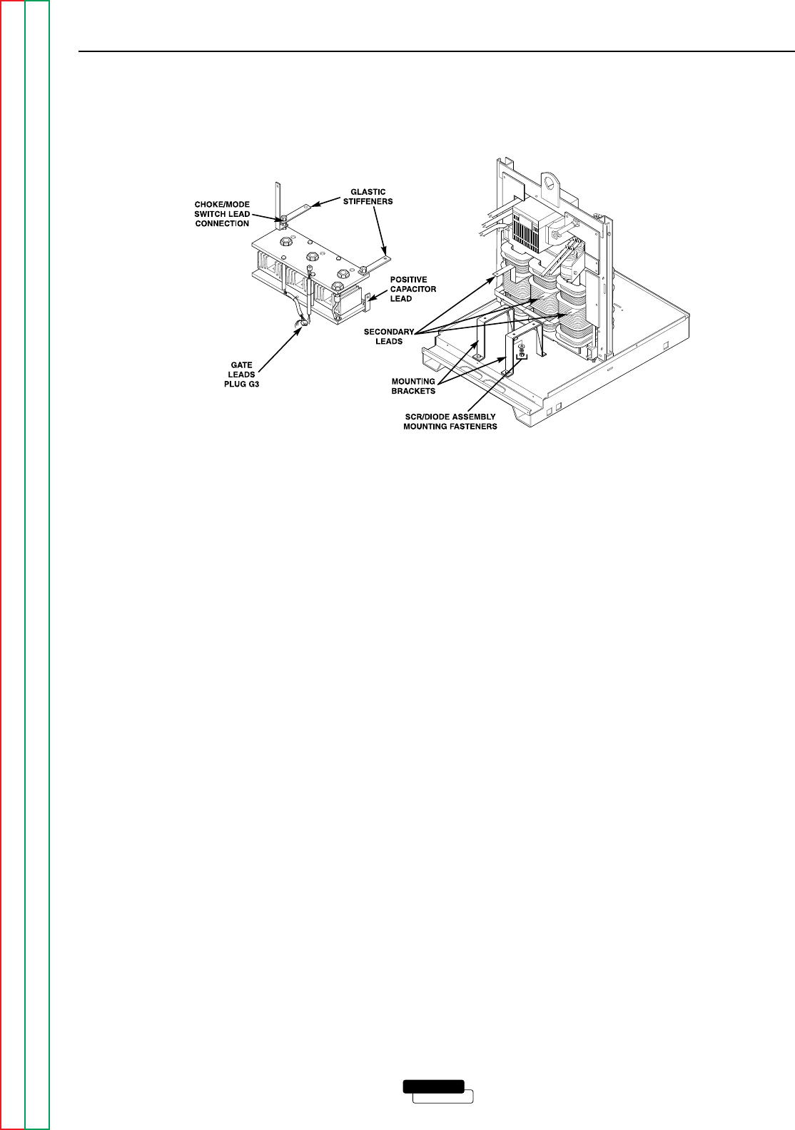
FIGURE F.19 – SCR/DIODE ASSEMBLY DETAILS
PROCEDURE
1. Remove the main input supply power to the
machine.
2. With the 5/16” nut driver, remove the case
top and sides.
3. Remove the glastic stiffeners (one on each
side-left and right). See Figure F.19.
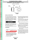
4. Remove the positive capacitor lead and
shunt from the positive heat sink plate. See
Figure F.19.
5. Remove the choke and mode switch lead
from the left side of the negative heat sink
plate. See Figure F.19.
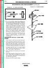
6. Remove the gate leads from the control
board (plug P3).
7. Remove plug P5 from the snubber board.
Also remove lead #224 from the positive
output lead. Remove lead #225 from the
negative output lead. Remove the green
ground lead from the front panel.
8. Remove the three heavy aluminum sec-
ondary leads from the SCR finned heat
sinks.
9. Remove the four nuts and associated wash-
ers that hold the SCR/diode assembly to the
mounting brackets.
10. Carefully lift and remove the SCR/diode heat
sink assembly from the machine. Note: It
may be necessary to loosen the six sheet
metal screws that hold the front panel to the
base. Carefully lift and pull out the front
panel to allow clearance for SCR/diode
assembly removal. Clear any necessary
leads that might hinder removal.
11. For reassembly, carefully place the SCR/
diode assembly into position on the mount-
ing bracket and reinstall the washers and
nuts. Tighten the front panel to base if it was
loosened earlier.
12. Replace and tighten the four nuts and lock-
washers that hold the SCR/diode assembly
to the mounting brackets.
13. Reattach the three heavy aluminum sec-
ondary leads to the SCR finned heat sinks.
Apply a thin coating of Dow Corning 340
heat sink compound (Lincoln E1868) to con-
nection points.
14. Connect the green ground lead to the front
panel, lead #225 to the negative output lead,
and lead #224 to the positive output lead.
15. Connect plug P5 to the snubber board and
plug P3 to the control board.
16. Connect the choke and mode switch lead to
the left side of the negative heat sink plate.
See Figure F.19.
17. Connect the positive capacitor lead and
shunt to the positive heat sink plate. See
Figure F.19.
18. Install the glastic stiffeners to the left and
right sides. See Figure F.19.
19. Install the case top and sides.