


Return to Section TOC Return to Section TOC Return to Section TOC Return to Section TOC
Return to Master TOC Return to Master TOC Return to Master TOC Return to Master TOC
OPERATION
B-5 B-5
LINCOLN
®
ELECTRIC
IDEALARC DC-400
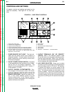
7. AUXILIARY POWER AND REMOTE CONTROL
CONNECTIONS FOR WIRE FEEDER AND
OTHER EQUIPMENT (115V AND 42V): The 14-
pin amphenol receptacle provides either 115 or
42 volts AC as well as remote control connec-
tions. Terminal strips with screw connections are
located behind the hinged control panel for hard
wired control. Only 115 volts AC is available on
the terminal strip. A strain relief connector is pro-
vided for cable entry.
8. MODE SWITCH: Selects between Constant
Voltage FCAW/GMAW and Constant Voltage
Submerged Arc (Red range on dial), and Constant
Current Stick/TIG (Blue range on dial).
9. ARC CONTROL: A five-position switch that
changes the pinch effect of the arc when in the CV
FCAW/GMAW mode. It allows control of spatter,
fluidity, and bead shape. The Arc Control is set to
provide optimum welding depending on the
process, position, and electrode. Pinch effect is
increased by turning the control clockwise. It can
also be adjusted while the machine is in opera-
tion.
10. THERMAL PROTECTION INDICATOR LIGHT:
This amber light indicates that either of the two
protective thermostats has opened. Output
power is removed, but input power is still being
applied to the machine.
11. DC AMMETER: Displays output current when
welding.
12. DC VOLTMETER: Displays output voltage when
welding.
13. VOLTMETER “+” ELECTRODE OR “-” ELEC-
TRODE SWITCH: Selects the electrode polarity
for the remote work sensing lead (#21) when using
automatic or semiautomatic wire feeders.