


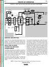

OUTPUT MODE AND CONTROL,
RECTIFICATION AND FEEDBACK
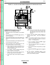
The three-phase AC output from the main transformer
secondary is rectified and controlled through the SCR/
diode bridge. Output current and voltage is sensed at
the shunt and output terminals. This feedback infor-
mation is processed in the control board. The control
board compares the commands of the Mode Switch,
the Arc Force Control (constant current mode only),
and the Output Control (or remote control) with the
feedback information and sends the appropriate gate
firing signals to the SCR/diode bridge.
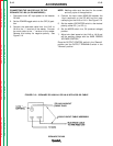
A “dry closure” of leads #2 and #4, either at the termi-
nal strip or the 14 pin amphenol, signals the control
board to apply gate firing signals to the SCR/ Diode
Bridge, which creates a DC voltage at the output of the
bridge assembly. If the Mode Switch is in the constant
voltage (FCAW/GMAW) mode, this DC voltage is fil-
tered by the Output Capacitors.
The heavy current carrying portion of the Mode
Switch is connected between the output choke,
which stores energy and provides current filtering,
and the negative output terminal. Depending upon
the mode selected, different portions of the choke are
needed. In the constant current mode (CC), the
entire choke is connected into the welding output cir-
cuit. When constant voltage (CV) is required, only
part of the choke is utilized.
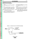
The starting circuit board function is to momentarily
change the inductance effect that the choke has on
the welding circuit. This is accomplished by changing
the amount of “pinch” or arc control windings that are
active in the output choke. When weld current is
established, the reed switch closes and the start board
becomes inactive.
THEORY OF OPERATION
E-3 E-3
LINCOLN
®
ELECTRIC
IDEALARC DC-400
Return to Section TOC Return to Section TOC Return to Section TOC Return to Section TOC
Return to Master TOC Return to Master TOC Return to Master TOC Return to Master TOC
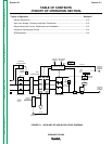
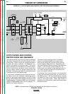
NOTE: Unshaded areas of Block Logic Diagram are the subject of discussion.
FIGURE E.3 – OUTPUT MODE AND CONTROL, RECTIFICATION AND FEEDBACK
FAN
115VAC
42VAC
14 PIN
AMPHENOL
REMOTE
CONTROL
TO
CONTROL
BOARD
CONTROL BOARD
OUTPUT
CONTROL
ARC FORCE
CONTROL
CONTROL
TRANSFORMER
POWER
SWITCH
R
E
C
O
N
N
E
C
T
INPUT
CONTACTOR
T
E
R
M
I
N
A
L
S
T
R
I
P
TRANSFORMER
MAIN
SCR DIODE
HYBRIDBRIDGE
/
PART
OF
MODE
SWITCH
CAPACITORS
SHUNT
REED
SWITCH
START
BOARD
PART
OF
MODE
SWITCH
OUTPUT
CHOKE
NEGATIVE
OUTPUT
TERMINAL
POSITIVE
OUTPUT
TERMINAL
PART OF
MODE
SWITCH
OUTPUT
G
A
T
E
S
I
G
N
A
L
S
FEEDBACK
F
E
E
D
B
A
C
K