


WELDING OPERATION
OPERATING STEPS
LOCAL CONTROL
The following procedures are for using the Idealarc
DC-400 in the local control mode of operation. For
remote control of the machine, see the REMOTE
CONTROL section.
Before operating the machine, make sure you have all
materials needed to complete the job. Be sure you are
familiar with and have taken all possible safety pre-
cautions before starting work. It is important that you
follow these operating steps each time you use the
machine.
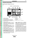
1. Turn on the main AC input power to the machine.
2. Set the VOLTMETER “+” or “-” switch to the
appropriate position.
• Set toggle to “´Electrode Negative” position if
the electrode is connected to the negative (-)
output terminal.
• Set toggle to “Electrode Positive” position if the
electrode is connected to the positive (+) output
terminal.
3. Set the welding MODE switch to welding process
being used.
• CV FCAW/GMAW
• CV Submerged Arc
• CC Stick/Tig
4. Set the OUTPUT CONTROL switch to “Local.”
(Exception: when using an LN-9, LN-9 GMA, or
NA-5 wire feeder, set the switch to “Remote.”
Otherwise, the wire feeder may automatically shut
down.
5. Set the OUTPUT TERMINALS switch to the
desired mode.
6. Set the ARC FORCE CONTROL to midrange, 5-6.
This control is for CC stick or TIG welding only.
Adjust for best characteristics as necessary.
7. Set the ARC CONTROL to midrange, 3. This con-
trol is for CV FCAW/GMAW welding only. Adjust
as necessary for best pinch control.
8. Set the ON/OFF POWER toggle switch to the ON
position (1).
• The power source pilot light glows.
• The fan starts.
9. Set OUTPUT CONTROL potentiometer to desired
voltage or current.
10. Make the weld.
REMOTE CONTROL
The toggle switch on the control panel labeled “Output
Control Remote” gives you the option of controlling
the machine output from a remote location. In the
“Remote” position a wire feeder with remote control
capabilities or a remote control device such as a K775
must be connected to the DC-400. Refer to the
Accessories section for wire feeder installation infor-
mation.
WELDING PROCEDURE RECOMMENDATIONS
Select Mode Switch position based on type of welding
to be done.
1. FCAW/GMAW Welding/Other Open Arc Processes:
Use the CV FCAW/GMAW mode.
2. Submerged Arc Welding: Use the CV Submerged
Arc mode. If performing high speed welding,
switch between the CV Submerged Arc and the CV
FCAW/GMAW mode and use the mode that pro-
duces the best welding results.
3. Air/Carbon Arc Cutting / Stick Welding / High
Current, Large Puddle Submerged Arc Welding:
Use the CC mode. When the Idealarc DC-400 is
used for Air/Carbon Arc cutting, the OUTPUT
CONTROL potentiometer should be set to “9” ini-
tially. Based on the size of the carbon being used
or the process, turn the potentiometer to a lower
setting as required by the process. You can use
carbon rods up to 5/16” (8 mm) in diameter at cur-
rents as high as 450 amps with excellent arc con-
trol. The welder protection circuit protects the
machine from extremely high short circuiting
pulses.
SEMIAUTOMATIC AND AUTOMATIC WIRE
FEEDING WITH AN IDEALARC DC-400
When using the Idealarc DC-400 with semiautomatic
or automatic wire feeding equipment and for stick
welding or air/carbon arc cutting, it is recommended
that the optional MULTIPROCESS switch be used.
This switch permits you to easily change the polarity of
the connected wire feeding equipment or switch to
stick welding or air/carbon arc cutting.
OPERATION
B-6 B-6
LINCOLN
®
ELECTRIC
IDEALARC DC-400
Return to Section TOC Return to Section TOC Return to Section TOC Return to Section TOC
Return to Master TOC Return to Master TOC Return to Master TOC Return to Master TOC