


Return to Section TOC Return to Section TOC Return to Section TOC Return to Section TOC
Return to Master TOC Return to Master TOC Return to Master TOC Return to Master TOC
INSTALLATION
A-8 A-8
LINCOLN
®
ELECTRIC
IDEALARC DC-400
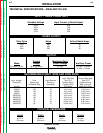
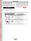
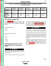
TABLE A.1 - CABLE SIZES FOR COMBINED LENGTHS OF COPPER ELECTRODE
AND WORK CABLES
Up to 50 ft 50 - 100 ft 100 - 150 ft 150 - 200 ft 200 - 250 ft
Machine Size (15 m) (15 - 30 m) (30 - 46 m) (46 - 61 m) (67 - 76 m)
400 Amp 3/0 3/0 3/0 3/0 4/0
(100% Duty 85 mm
2
85 mm
2
85 mm
2
85 mm
2
107 mm
2
Cycle)
500 Amp 2/0 2/0 3/0 3/0 4/0
(50% Duty 67 mm
2
67 mm
2
85 mm
2
85 mm
2
107 mm
2
Cycle)
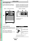
WIRE FEEDER CONNECTIONS
See the Accessories section of this manual for spe-
cific instructions on connecting the following semi-
automatic and automatic wire feeders to the Idealarc
DC-400:
Automatic Wire Feeders:
• NA-3
• NA-5
Semi-automatic Wire Feeders:
• LN-7
• LN-8
• LN-9
• LN-25
• LN-742
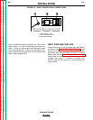
CONNECTIONS FOR STICK, TIG, OR
AIR/CARBON ARC CUTTING OPERA-
TIONS
The output terminals are energized at all times when
the Idealarc DC-400 is used for stick, TIG, or air/car-
bon arc cutting.
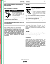
The work and electrode cables for stick, TIG, or
air/carbon arc cutting are connected as described ear-
lier, under the heading Output Connections. A TIG
torch is connected to the electrode (+) terminal of the
welder. Select cable size according to Table A.1.
Do not connect a TIG torch and stick electrode cable
at the same time. They will both be electrically HOT.
If the Idealarc DC-400 is already set up for wire feeder
operation, all wire feeder unit control, electrode, and
work cables must be disconnected first before you
can connect the cables for stick, TIG, or air/carbon arc
operation.
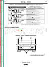
However, the Idealarc DC-400 can be used for both
wire feeder operation and stick, TIG, air/carbon arc
operation if a K804-1 Multiprocess Switch is used.
See the Accessories section of this manual for spe-
cific instructions on connecting and using the
Multiprocess Switch.
WARNING
WARNING
96OCT