


3
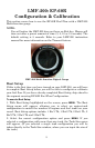
LowranceNET Node Kit for a NMEA 2000 network. Includes a 2-foot
extension cable, T connector and two 120-ohm terminators.
For complete instructions on setting up a new NMEA 2000 network or
expanding an existing one, see the other document packed with your
EP-60R Fuel Flow, "Setup and Installation of NMEA 2000 Networks,
General Information" part number 988-0154-173. If that document is
unavailable, it can be downloaded free from the Lowrance web site.
Other supplies are not included, unless otherwise indicated. Required
supplies include cable ties or other fasteners to secure the hose and
cable; an inline fuel filter and any items needed to install it. Two 1"
hose clamps are included with the sensor.
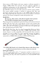
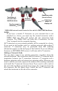
We assume you already have a fuel line installed. The EP-60R Fuel
Flow was designed to fit a typical 3/8" SAE USCG Type A1 fuel hose. If
your engine has different diameter hoses or metal fuel lines, a section
of 3/8" fuel line must be installed between the sensor and the existing
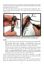
lines. Recommended tools are a flathead screwdriver to tighten the
clamps and a knife to cut the fuel hose. If you need to route the sensor
connector through a bulkhead, you will need a drill and a 3/4" drill bit.
Installation
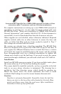
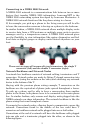
Install one EP-60R sensor per engine. If you have multiple tanks, place
the sensor after any Y or T in the line feeding the engine.
The sensor should be installed vertically, as close as possible to the fuel
tank in an area where vibration is minimized. The housing has a
molded-in, fuel flow direction arrow, which should be pointing up.
Mount the sensor above the tank's maximum fuel level to avoid
accidental fuel leakage in case the sensor becomes disconnected.
Caution:
Gasoline is extremely flammable. If possible, drain the fuel line
before you start or shut any flow valves located at the tank. Keep
sparks and flame away from the work area. After installation,
remember to clean up any spilled fuel.