


P 10/ 30
Repair
[3] DISASSEMBLY/ASSEMBLY
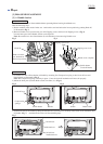
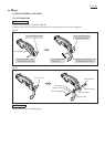
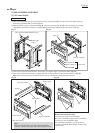
Fig. 23
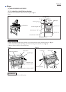
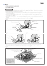
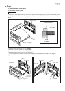
Fig. 24 Fig. 25
ASSEMBLING
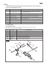
[3] -5. Blade Case Section (cont.)
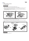
Slide Sleeve 13 as far as possible toward Steel ball 6. At this time, the distance between Sleeve 13 and the neck of
Knob 40 will be about 7mm. While keeping the distance, secure Connecting rod to Sleeve 13 with Hex socket head bolt
M6x30. (Fig. 23)
1. When installing Sleeve 13 and Connecting rod on Knob 40;
2. When installing Link plate and Safety cover on Blade case;
Do the reverse step of disassembling steps. Remember the following notes.
Steel ball 6
on Knob 40
Sleeve 13
Adjust nut
Knob 40
7mm
Sleeve 6
Connecting rod
Flat washer 6
Hex socket head
bolt M6x30
Blade case
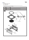
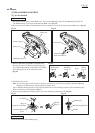
As illustrated in Fig. 24, put Link plate on Ball bearing 608LLB that is mounted to the inside wall of Blade case for
smooth action of Link plate. Then secure Link plate to Arm complete with Hex socket head bolt M6x20. (Fig. 20)
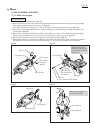
On the back of Safety cover, there is a rib that acts as a guide rail for the Ball bearing on Link plate.
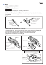
Mount Safety cover to Bearing box so that the Ball bearing of Link plate fits on the rib. (Fig. 25)
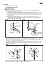
And secure Safety cover with Retaining ring S-42. (Fig. 14)
Rib
Ball bearing
of Link plate
Tension spring 4
Tension spring 4
Ball bearing
608LLB
Ball bearing
(integral part of Link plate)
Link plate
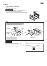
Rib
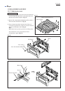
Safety cover and Link plate correctly set in place,
viewed from the Motor housing side
Link plate
Blade case
Safety cover
Safety cover