


P 8 / 30
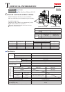
Repair
[3] DISASSEMBLY/ASSEMBLY
[3] -4. Gear Section
Fig. 17
Fig. 15
Fig. 18
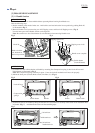
DISASSEMBLING
Fig. 14
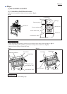
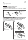
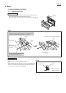
1) Disconnect Tension spring 4 from Blade case. By removing Retaining ring S-42 with Retaining pliers ST-2N
(No.1R003), Safety cover can be separated from Blade case. (Fig. 14)
2) By unscrewing four M5x16 Countersunk head screws, the Gear section can be separated from Blade case. (Fig. 15)
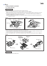
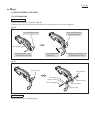
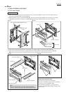
3) Remove Ball bearing 608LLB from Spindle with
Bearing extractor (No.1R269), then Retaining ring
S-15 with Retaining Ring S and R Pliers (No.1R291).
Now Helical gear 46 can be removed by hand.
(Fig. 16)
4) Fix Bearing box in vise.
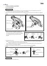
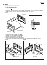
Note: It is not necessary to remove Ring 15 in this step because it can be used as a guide for Wrench for Bearing
Retainer (No.1R340) when removing Bearing retainer 25-36.
Set No.1R340 on Bearing retainer 25-36, and turn clockwise to remove Bearing retainer 25-36 from Bearing box.
Then remove Ring 15 from Spindle. (Fig. 17)
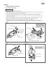
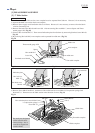
5) When removing Spindle from Bearing box, press from the Flange installation side. (Fig. 18)
Retaining ring S-42
Safety cover
Tension spring 4
Countersunk
head screw M5x16
Gear section
No.1R340
Ring 15
(guide for No.1R340)
Ring 15
Spindle
Bearing retainer
25-36
ASSEMBLING
Do the reverse of the disassembling steps.
Blade case
Ball bearing 6202LLB
Spindle
Bearing box
Fig. 16
Ball bearing
608LLB
Retaining
ring S-15
Helical
gear 46
Key 4