


P 15/ 30
Repair
[3] DISASSEMBLY/ASSEMBLY
[3] -8. Frame Section
Fig. 37
Fig. 39
Fig. 38
Fig. 40
DISASSEMBLING
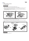
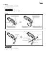
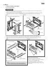
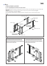
1) After removing Switch box, place the Frame section as illustrated in Fig. 37, and remove four Square pipes by
unscrewing eight M8x20 Hex socket head bolts.
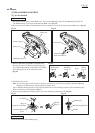
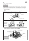
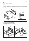
2) Place the Frame section as illustrated in Fig. 38. Then, by removing four M10 Hex nuts from Pipe 32 complete
(with Makita mark label) and Pipe 32 (without Makita mark label), separate right Frame from left Frame.
Hex socket head bolt M8x20 (8 pcs)
Square pipe
(4 pcs)
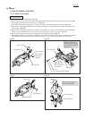
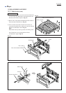
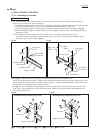
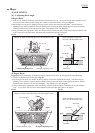
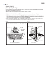
3) From each of *right and *left Frames, remove Pipe 32 complete (Pipe 32) and Screw M10. (Fig. 39)
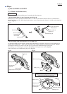
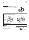
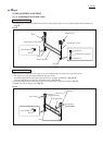
4) Caps can be removed from Frame by tapping the joint of Cap and Frame with slotted screwdriver. (Fig. 40)
Note: Do not reuse Caps removed from Frame because it is deformed or damaged when removed.
Pipe 32
Pipe 32 complete
Screw M10
Cap
Hex nut M10
Spring washer 10
Flat washer 10
Pipe 32 complete
(4 pcs each)
Frame, right
Frame, left
Pipe 32
Note:
This end of Screw M10 is screwed in the threaded hole
of Frame. Therefore, unscrew when removing from Frame.
Cap
(See Note below.)
(See Note below.)
*Right Frame and Left Frame;
Are exactly the same in size and shape.
However, some different parts such as Switch box
or Lock lever are assembled to them.
For convenience, therefore, we call the one on
operator's right hand "Right Frame" and the other
"Left Frame".