


P 29/ 30
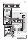
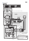
Wiring diagram
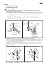
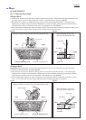
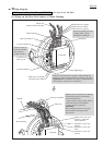
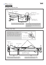
[2] Wiring in Handle
UK-110V
Switch
Line filter
Strain relief
10 - 20mm
10 - 20mm
Connecting cord
from Switch box
L-shaped ribInside wall A
Lead wires from
Controller and Field
Band
Noise
suppressor
Be careful not to
route lead wires
over Strain relief.
Put Line filter between Strain relief and Band.
Install Connecting cord and Band on Handle so that;
*the distance between the end of Connecting cord and the inside wall A is 10 - 20mm
*the distance between the end of Connecting cord and Band is 10 - 20mm.
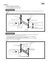
Route the three lead wires to Switch between
the L-shaped rib and the inside wall A.