


P 9 / 30
Repair
[3] DISASSEMBLY/ASSEMBLY
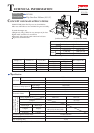
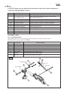
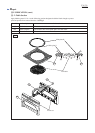
[3] -5. Blade Case Section
Fig. 21 Fig. 22
DISASSEMBLING
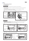
Fig. 19 Fig. 20
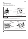
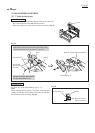
1) Remove Safety cover as illustrated in Fig. 14.
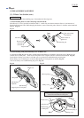
2) Remove Dust nozzle. Then remove Hex socket head bolt M6x30 and Flat washer 6 for disconnecting the cutting
depth adjusting mechanism and Connecting rod. (Fig. 19)
3) Loosen Hex nut M10 on Connecting rod. But do not remove from Connecting rod in this step. (Fig. 19)
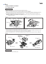
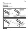
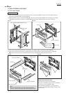
4) Remove Hex socket head bolt M6x20, Flat washer 6 and Ring 6 for disconnecting the linkage of Link plate and
Arm complete. (Fig. 20)
5) Remove Hex socket head bolt M5x20 and Sleeve 5 from Blade case with 1/4" Hex shank bit for M6 (No.1R230)
while pressing down Blade case so that it is not raised by the force of Torsion spring 34. (Fig. 20)
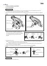
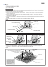
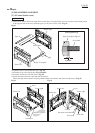
6) Disconnect Connecting rod from Arm complete by removing Hex nut M10. (Fig. 21)
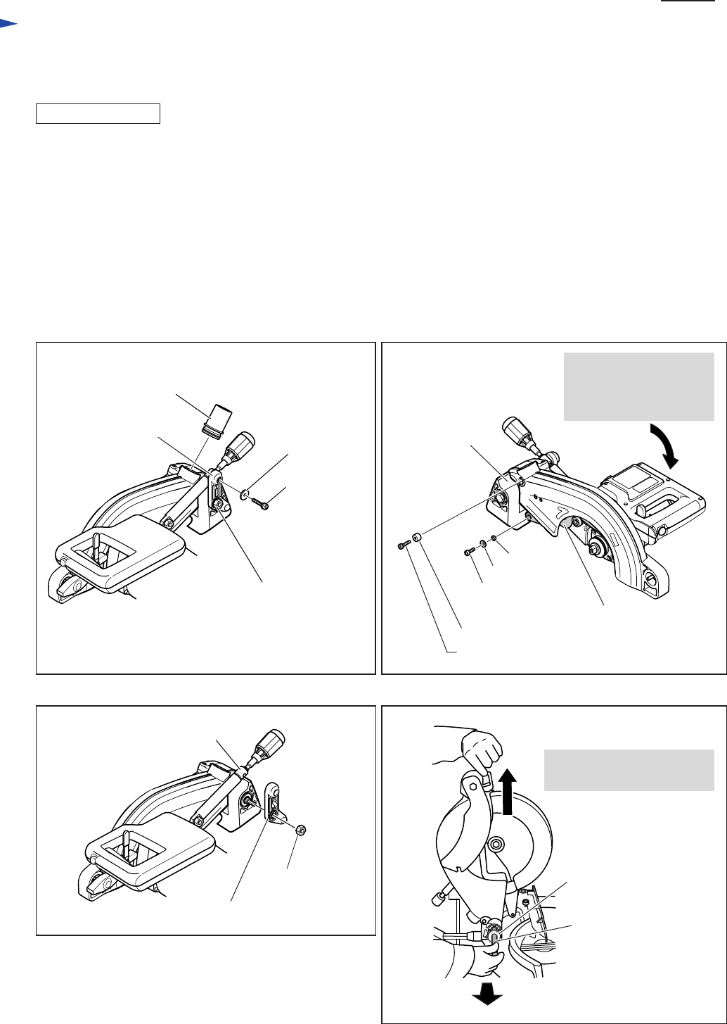
7) While holding Blade case as illustrated in Fig. 22, remove Hex bolt M10 and Flat washer 16 from Arm complete.
Now Blade case section with Torsion spring 34 and Sleeve 17 (2pcs) can be separated from Arm complete.
Hex socket
head bolt
M6x30
Hex socket head
bolt M6x20
Flat washer 6
Sleeve 5
Hex socket head bolt M5x20
Flat washer 6
Ring 6
Link plate
Arm complete
While pressing down
Blade case, remove Hex
socket head bolt M5x20
and Sleeve 5.
Dust nozzle
Hex nut M10
Connecting rod
Hex nut M10
Sleeve 13
Connecting rod
Hex bolt M10
Flat washer 16
While lifting up Blade case,
pull off hex bolt M10.