


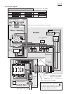
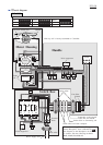
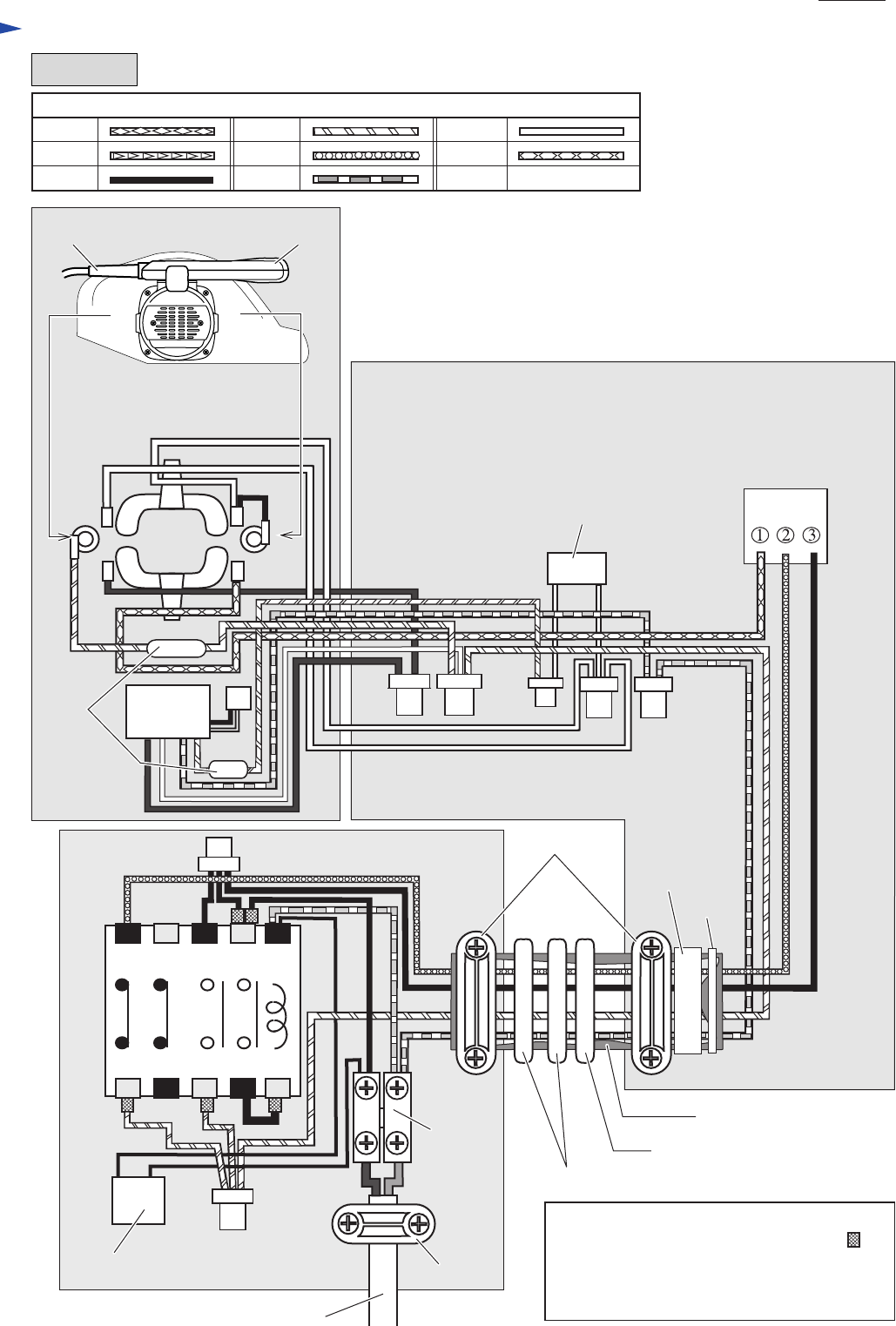
Circuit diagram
P 23/ 30
UK-110V
Color index of lead wires' sheath
Black
White
Red
OrangeBlue
Brown Purple Yellow
*Pick up coil is factory-assembled to Controller.
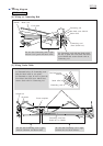
When Connecting Wires to Relay;
Attach Receptacle sleeve (indicated by in
the diagram) to the Receptacle on the wires
to connect with the following terminals:
No.5, No.42, No.4 No.A2
A153141
A264242
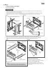
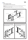
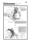
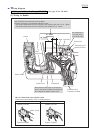
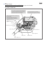
Motor Housing
Switch Box
Handle
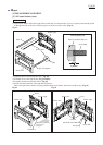
A B
A
B
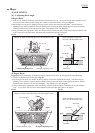
Cord from Switch box
Handle
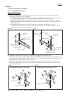
Strain relief
Strain relief
Band
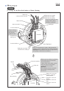
Choke
coil
Connecting code between
switch box and handle
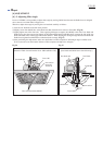
Noise suppressor
Noise suppressor
Switch
Field
Relay
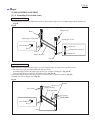
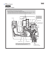
Strain relief on Frame complete
Strain relief on Connecting rod
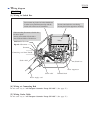
Line filter
Terminal
block
Controller
Power supply cord