


P 16/ 30
Repair
[3] DISASSEMBLY/ASSEMBLY
[3] -8. Frame Section (cont.)
ASSEMBLING
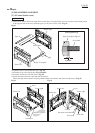
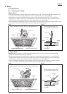
Fig. 41
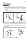
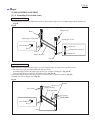
Fig. 42 Fig. 43
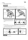
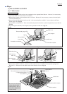
1) Fasten Screw M10 to left Frame/ right Frame so that Pipe 32 complete/ Pipe 32 covers 2 pitches of the thread portion
on the opposite side of the screw when the pipe is set in place over the screw. (Fig. 41)
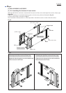
2) Tighten Frames with four M10 Hex nuts. (Fig. 38)
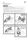
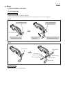
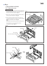
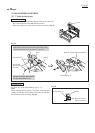
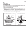
3) Assemble Lever to the right Frame. (Fig. 35 and 42)
4) Assemble Switch box to the left Frame. (Fig. 42)
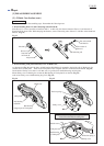
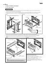
5) Install each three Cushions to the right and left Frames.
Then to the right frame, fasten Leaf spring with Pan head screw M4x10, and fasten two M6 screws. (Fig. 43)
Operator's position
Switch box
Lever
Frame, left
Frame, right
Lever
Switch box
Frame, left
Frame, right
Cushion
Leaf spring
Screw M6
Pan head screw M4x10
Pipe 32
Pipe 32 complete
Screw M10
Frame, right
Frame, left
Pipe 32 complete (Pipe 32)
Screw M10
2 pitches
[A]
Cross section of [A]