


P 14/ 30
Repair
[3] DISASSEMBLY/ASSEMBLY
DISASSEMBLING
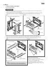
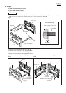
[3] -7. Table Section (cont.)
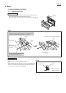
Fig. 35
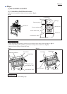
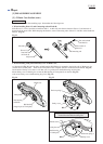
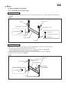
9) Lever (Lock lever) is fastened to Frame with each two pieces of
Hex socket button head bolt M6 and Flat washer 7.
When removing Lever, follow the instruction described in Fig. 35.
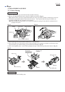
Hex socket
button head
bolt M6
Lever
Flat washer 7
Torsion spring 17
Boss for Torsion spring installation
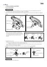
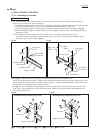
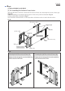
ASSEMBLING
Do the reverse of the disassembling steps 1) - 9).
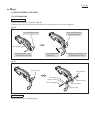
Note:
When installing Torsion spring 17 on Frame, insert the spring
straight over the boss till it touches the inside wall of Frame.
Be careful not to tilt the spring. (Fig. 36)
Frame
Boss for Torsion
spring installation
Torsion spring 17
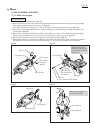
Fig. 36
Frame
Lever
If this bolt is removed first, the force of Torsion spring
will cause the Bolt and Flat washer 7 to pop off.
Be sure to remove this bolt first
for easy removal of Lever.