


P 28/ 30
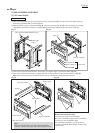
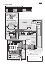
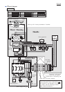
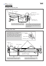
Wiring diagram
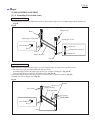
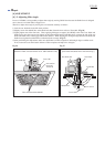
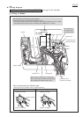
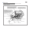
Lead wire holder D
Motor housing
Motor housing
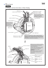
Choke coil,
connected with Controller
Choke coil
Controller
Controller
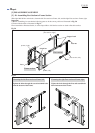
Opening B
Opening A
Field lead wire (orange)
Field lead wire (black)
Field lead wire (yellow)
Field lead wire (white)
Field lead wire (white)
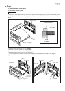
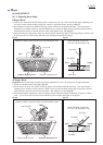
Lead wires of
Pick up coil
Fix two wires of
Pick up coil with
the lead wire
holders B and C.
Handle
Lead wire holder B
Lead wire holder A
Route two Field lead wires (white, white) through the
opening A, and fix with the lead wire holders A, B and C.
Important: Be sure that the lead wires are tight between
the opening A and the lead wire holder C.
Route three Field lead wires
(orange, black, yellow)
through the opening B.
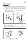
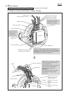
[1] Wiring on the Rear End Surface of Motor Housing
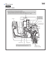
Choke-coil's lead wire
(orange), connected
with Controller
Controller's lead wire
(black)
Controller's lead wire
(red)
Controller's lead wire
(white)
UK-110V
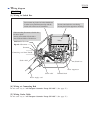
With the lead wire holder D on Handle,
fix the following lead wire holders:
*five Field lead wires
(white, white, orange, black, yellow)
*four lead wires from Controller
(orange, black, red, white)
Important:
Be sure that the nine wires are tight
between Motor housing and the
lead wire D.
Lead wire holder C