


P 5 / 30
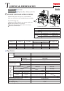
Repair
[3] DISASSEMBLY/ASSEMBLY
[3] -1. Handle Section
Fig. 4
Fig. 3
Fig. 5
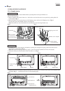
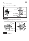
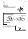
DISASSEMBLING
The Handle section can be disassembled without separating Motor housing from Blade case.
Take the following steps:
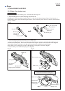
1) Set the machine in the mode of miter saw. And lock the saw head unit at the lowest position by pushing Knob 20
as illustrated in Fig. 3.
2) Remove Handle cover by unscrewing two 4x25 Tapping screws and four 4x18 Tapping screws. (Fig. 4)
Now the inner parts of the Handle section can be replaced.
Note: Be careful not to lose Switch button (Lock off button) when removing Handle cover.
Knob 20
Push to lock the
saw head unit at
the lowest position.
Switch button
(Lock off button)
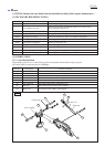
Handle cover complete
Tapping screw 4x25
Tapping screw 4x18
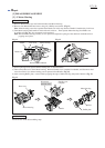
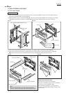
ASSEMBLING
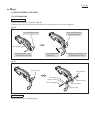
1) Assemble Now lock-off mechanism to Handle by mounting first Compression spring 4, then Lock-off lever and
Switch button as illustrated in Fig. 5.
Note: Put Compression spring 4 securely in place. If not, the lock-off mechanism will not work properly.
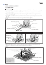
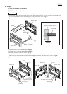
2) Mount the inner parts (Switch, Brake switch, Line filter, etc). (Fig. 6)
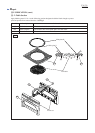
Compression
spring 4
Lock-off lever
Switch button
Fig. 6
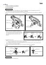
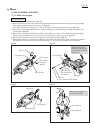
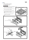
3) Install Switch lever on Handle by fitting the fulcrum boss on Switch lever securely in the switch lever installation hole
of Handle. (Fig. 7) And then do the reverse of disassembling steps.
Fig. 7
fulcrum boss
Switch lever
Switch lever
installation hole
Handle
Switch Brake switch