


P 12/ 30
Repair
[3] DISASSEMBLY/ASSEMBLY
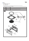
[3] -7. Table Section
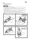
Fig. 29 Fig. 30
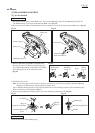
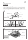
Fig. 28
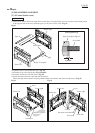
DISASSEMBLING
Pan head screw M4x10
Pan head screw
M4x10
Thrust needle gauge 1022
Lever 100
Hex nut M10-17
Spacer
Arm complete
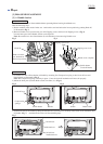
When disassembling the Table section, Arm complete has to be separated from Sub arm. However, it is not necessary
to separate the Blade case section from Arm complete.
1) Remove Power supply cord from Strain relieves on Frame. However, it is not necessary to remove from the Strain
relief on Connecting rod.
2) Remove Pan head screw M4x10 and Lever 100. After unscrewing Hex nut M10-17, remove Spacer and Thrust
needle gauge 1022. (Fig. 28)
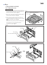
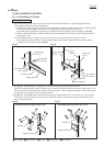
3) Unscrew Hex lock nut M10-17. Then remove Indication plate from Sub arm by unscrewing Pan head screw M4x10.
(Fig. 29)
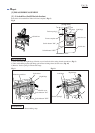
4) By removing Hex bolt M10, Arm complete can be separated from Sub arm. (Fig. 30)
Sub arm
Turn table complete
Hex lock nut
M10-17
Indication plate
Hex bolt M10
Blade case
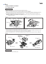
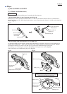
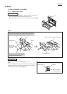
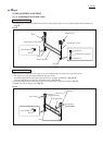
Fig. 31
Screw M6x25
Guide fence
Turn table complete
Hex socket head set screw M10x12
* Compression spring 6
* Steel ball 7.9
* Pin 5
Sub arm
Table complete
The small parts designated
with an asterisk can be
removed using a bar or
screwdriver magnetized
with No.1R288.
5) Remove Screw M6x25 and Pin 5. And remove Hex socket head set screw M10x12, Compression spring 6 and
Steel ball 7.9. Then turn over the Table section in the direction of arrow. (Fig. 31)