


5 - 20
5 Dedicated Options
MITSUBISHI CNC
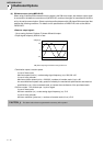
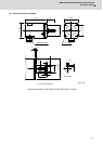
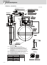
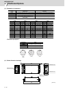
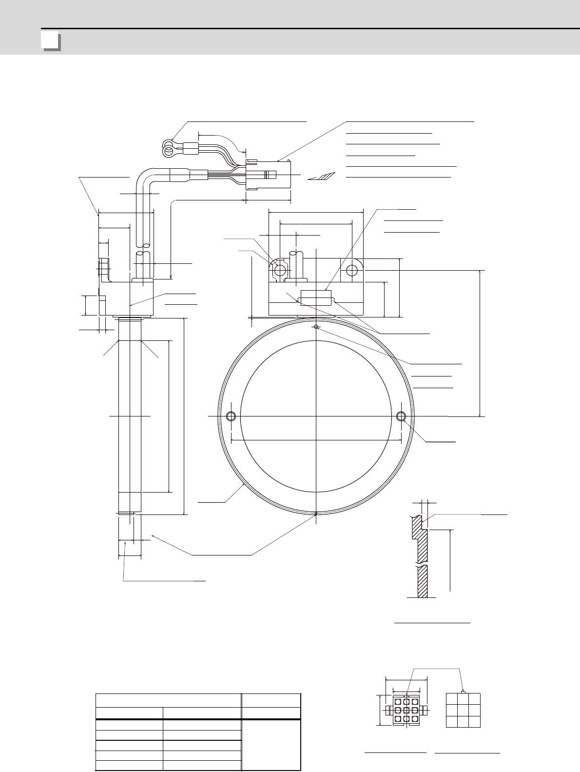
<TS5690N12xx + MU1606N709>
[Unit: mm]
RQ
MT1
987
456
321
MT2
RQ*
SDSD*
+5V
5G
FG
Ǿ122±0.025
16
22
3
48
12
Ǿ80H5
90
14
14.5
5.5
77
C0.5
C0.5
Ǿ7
29
A
23.7
100±10
A
5
R1
16.5
18.7
31.1
3.3
10.3
2-Ǿ5.8
38
50
0.3
±
0.05
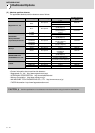
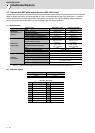
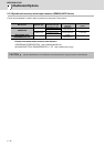
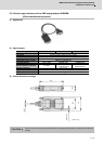
MU1606N709
1200±20
1600±30
2000±30
TS5690N1220
TS5690N1230
TS5690N1240
TS5690N1260
TS5690N1210
800±20
400±10
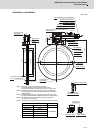
Detection gear outer DIA Ǿ104
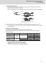
Round crimp contact for thermistor 0.5-4
(For M4 screw)
Output connector (by Tyco Electronics)
Housing (Cap) #172161-1
Contact (Socket) #170365-4
Accessories (Note 5)
Housing (Plug) #172169-1 Qty: 1
Contact (Pin) #170363-4 Qty: 9
Name plate
Sensor model and
Serial No. written
Ground
Gap
C part (Note 2)
D part (Note 3)
Ǿ2 hole for
identification
2-M5 screw
Sensor mounting face
Encoder mounting face
of machine side
Projection for
connector lock
Seen from Arrow A
Pin layout of output
connector
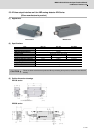
Sensor
Parts name
Lead wire length A
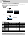
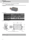
Detection gear
Parts name
The number of teeth 128
(For A, B phase signals)
One notch (For Z
phase signal)
Detection
gear
Central line of
detection gear
(Note 4)
Sensor mounting
face (Note 4)
(Note 1)
Handle with care as this is a precision component.
Pay special attention not to apply excessive external force
on the sensor’s detection face. Applying such force will cause a fault.
In installing the sensor, keep the protruding fitting of Ǿ122±0.025
on the machine side, and push the C part of the sensor mounting seat
against the fitting.
In installing the detection gear, make sure that the D part side comes
the opposite side of the sensor installation side (sensor’s lead wire side).
The diviation of the center of the detection gear is 16.5±0.25mm
from the sensor mounting face.
A connector of the signal cable side (one plug and nine pins) is attached.
(Note 2)
(Note 3)
(Note 4)
(Note 5)