


7 - 11
MDS-D-SVJ3/SPJ3 Series Specifications Manual
7-1 Selection of the servomotor
7-1-3 Motor shaft conversion load torque
The calculation method for a representative load torque is shown.
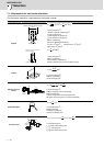
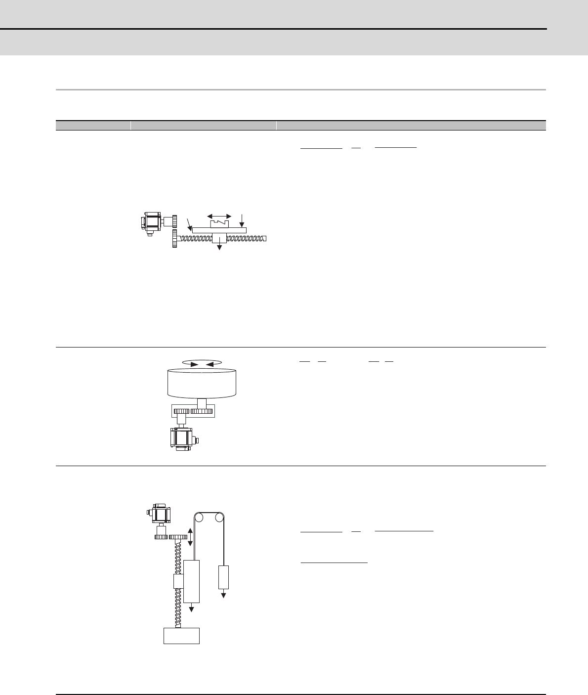
Type Mechanism Calculation expression
Linear
movement
T
L
:Load torque(N•m)
F:Force in axial direction of the machine that moves linearly(N)
η: Drive system efficiency
V:Speed of object that moves linearly(mm/min)
N:Motor speed(r/min)
ΔS:Object movement amount per motor rotation(mm)
Z
1
,Z
2
:Deceleration ratio
F in the above expression is obtained from the expression below when
the table is moved as shown on the left.
F=Fc+μ(W•g+F
0
)
F
c
:Force applied on axial direction of moving section (N)
F
0
:Tightening force on inner surface of table guide (N)
W:Total mass of moving section (kg)
g:Gravitational acceleration = 9.8 (m/s
2
)
μ:Friction coefficient
Rotary
movement
T
L
:Load torque(N•m)
T
L0
:Load torque on load shaft(N•m)
T
F
:Motor shaft conversion load friction torque(N•m)
η:Drive system efficiency
Z
1
,Z
2
:Deceleration ratio
n:Deceleration ratio
Vertical
movement
When rising T
L
=T
U
+T
F
When lowering T
L
= -T
U
•η
2
+T
F
T
L
:Load torque(N•m)
T
U
:Unbalanced torque(N•m)
T
F
:Friction torque on moving section(N•m)
W
1
:Load mass(kg)
W
2
:Counterweight mass(kg)
η: Drive system efficiency
g:Gravitational acceleration = 9.8(m/s
2
)
V:Speed of object that moves linearly(mm/min)
N:Motor speed(r/min)
ΔS:Object movement amount per motor rotation(mm)
μ:Friction coefficient
Z
2
W
F
0
F
c
Z
1
ǯ
Servo-
motor
T
L
=
F
10
3
πη
N
.
( ) =
V
10
3
πη
F
.
ΔS
Servomotor
Z
2
Z1
TL0
T
L
=
. .
T
L0+TF =
. .
TL0+TF
η
1
Z
1
n
1
η
1
Z
2
1/n
W
1
W
2
Servomotor
Counter-
weight
Load
T
U
=
(W
1
-W
2
)
.
g
10
3
πη
N
.
( ) =
V
10
3
πη
(W
1
-W
2
)
.
g
.
ΔS
T
F
=
10
3
πη
μ
.
(W
1
+W
2
)
.
g
.
ΔS