


MDS-D/DH Series Specifications Manual
Appendix 6-2 Notes for AC servo/spindle system
Appendix 6 - 7
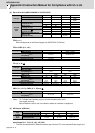
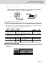
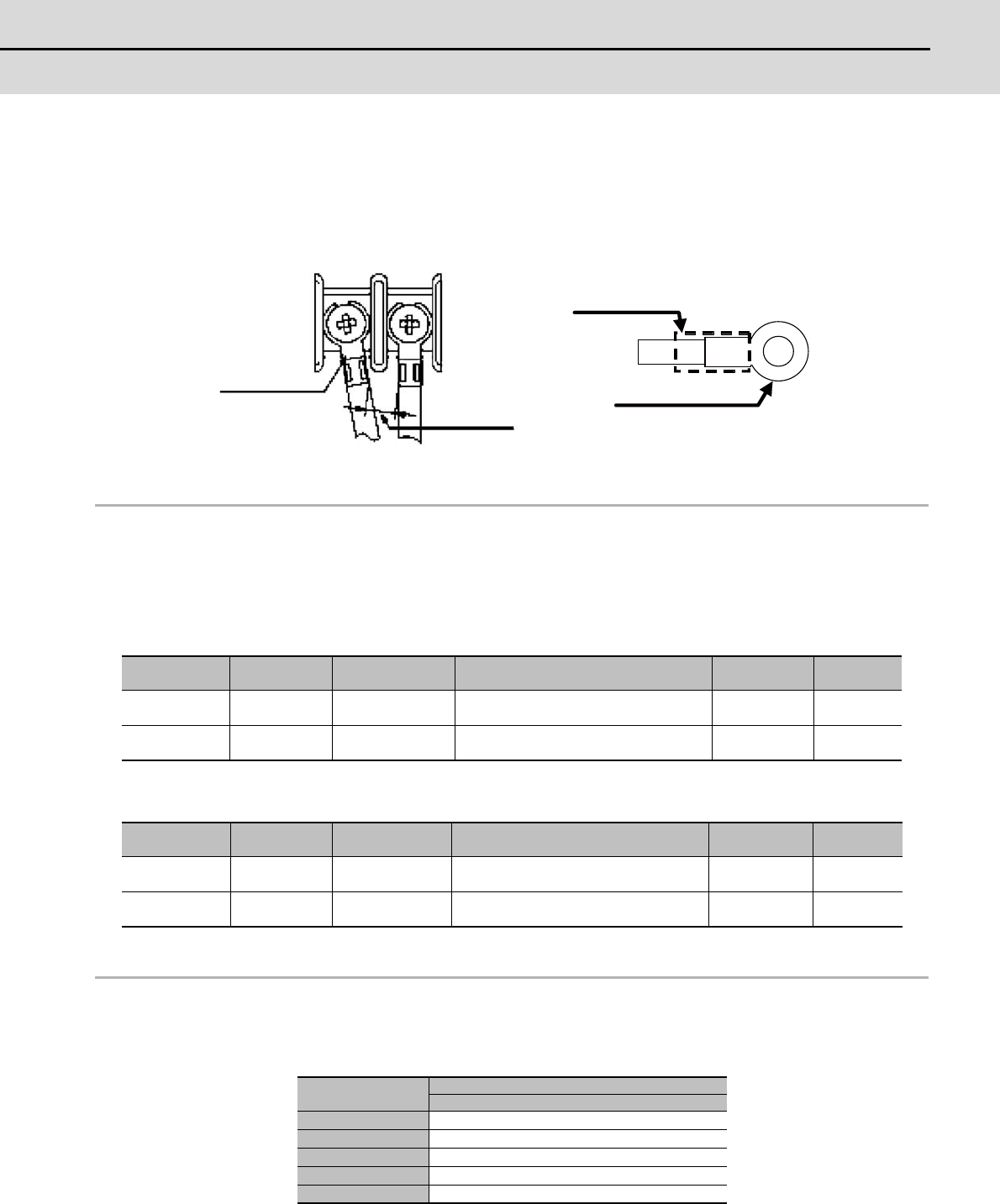
(5) Notes of Round Crimping Terminals and Terminal Block
The non-insulation ring tongue must have the insulated sleeving described below to prevent electric
shock.
The insulated sleeve must be provided with SUMITOMO ELECTRIC FINE POLYMER INC. (File No.:
E48762, Catalogue No.: SUMITUBE F(Z) or 939) per the illustration below.
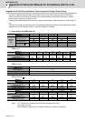
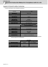
Appendix 6-2-6 Motor Over Load Protection
Spindle drive unit MDS-D/DH-SP/SP2/SPJ3 and Servo drive unit MDS-D/DH/DM-V1/V2/V3/SVJ3 series
have each solid-state motor over load protection. (The motor full load current is the same as rated current.)
When adjusting the level of motor over load, set the parameter as follows.
(1) MDS-D/DH-SP/SP2/SPJ3 (Spindle drive unit)
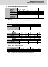
(2) MDS-D/DH/DM-V1/V2/V3/SVJ3 (Servo drive unit)
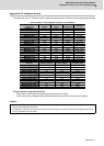
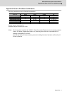
Appendix 6-2-7 Flange of servo motor
Mount the servo motor on a flange which has the following size or produces an equivalent or higher heat
dissipation effect:
Parameter
No.
Parameter
abbr.
Parameter
Name
Setting Procedure
Standard
Setting Value
Setting
Range
SP021 OLT*
Overload
time constant
Set the time constant for overload detec-
tion. (Unit: 1 second.)
60s 0 to 15300s
SP022 OLL
Overload
detection level
Set the overload current detection level
with a percentage (%) of the rating.
120% 1 to 200%
Parameter
No.
Parameter
abbr.
Parameter
Name
Setting Procedure
Standard
Setting Value
Setting
Range
SV021 OLT
Overload
time constant
Set the time constant for overload detec-
tion. (Unit: 1 second.)
60s 1 to 300s
SV022 OLL
Overload
detection level
Set the overload current detection level
with a percentage (%) of the stall rating.
150% 1 to 500%
Flange size
(mm)
Servo Motor
HF, HF-H, HP, HP-H, HF-KP, HF-MP, HF-SP
150x150x6 50 to 100W
250x250x6 200 to 400W
250x250x12 0.5 to 1.5kW
300x300x20 2.0 to 7.0kW
800x800x35 9.0 to 11.0kW
Insulated sleeve
Non-insulated terminal
Insulation
distance
Non-insulated
terminal