


7 - 9
MDS-D-SVJ3/SPJ3 Series Specifications Manual
7-1 Selection of the servomotor
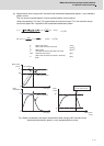
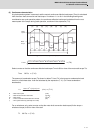
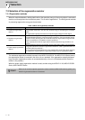
(3) Continuous characteristics
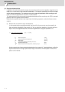
A typical operation pattern is assumed, and the motor's continuous effective load torque (Trms) is calculated
from the motor shaft conversion and load torque. If numbers <1> to <8> in the following drawing were
considered a one cycle operation pattern, the continuous effective load torque is obtained from the root
mean square of the torque during each operation, as shown in the expression (7-9).
Fig. 1 Continuous operation pattern
••• (7-9)
Select a motor so that the continuous effective load torque Trms is 80% or less of the motor stall torque Tst.
Trms 0.8•Tst ••• (7-10)
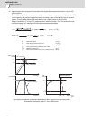
The amount of acceleration torque (Ta) shown in tables 7-3 and 7-4 is the torque to accelerate the load
inertia in a frictionless state. It can be calculated by the expression (7-11). (For linear acceleration/
deceleration)
••• (7-11)
For an unbalance axis, select a motor so that the motor shaft conversion load torque (friction torque +
unbalance torque) is 60% or less of the stall.
TL 0.6•Tst ••• (7-12)
N : Motor reach speed (r/min)
J
L
: Motor shaft conversion load inertia
(kg•cm
2
)
J
M
: Motor inertia
(kg•cm
2
)
ta : Linear acceleration/deceleration time constant (ms)
η : Drive system efficiency (Normally 0.8 to 0.95)
0
0
T3
T2
t1 t2 t3 t4
t0
T1
T4
T5
T6
T7
T8
t5 t6 t7 t8
[1]
[2]
[3]
[4]
[5]
[6]
[7]
[8]
Motor
torque
Motor
speed
Time
Trms =
T1
2
·t
1+T2
2
·t2
+T3
2
·t3
+T4
2
·t4
+T5
2
·t5
+T6
2
·t6
+T7
2
·t7
+T8
2
·t8
t0
T
a
=
ta
1.0510
-2
(J
L
/
η+
J
M
)N
(N
.
m)