Appendix 1 - 8
Appendix 1 Cable and Connector Specifications
MITSUBISHI CNC
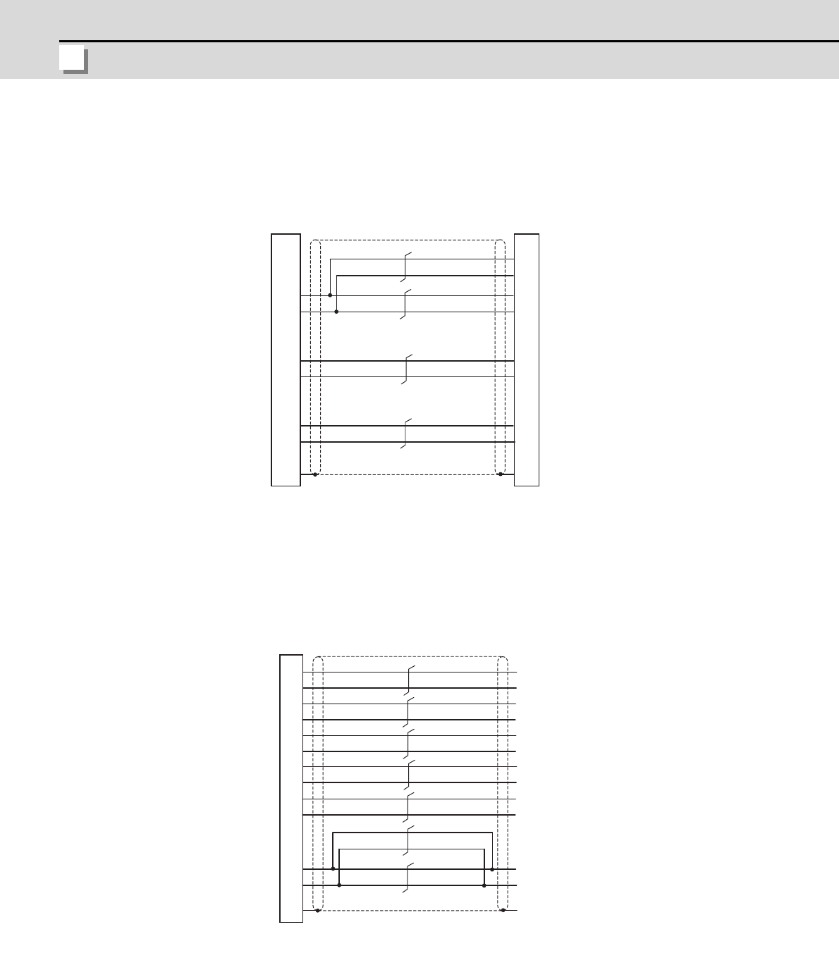
<CNV2E-HP cable connection diagram>
<Cable connection diagram between scale I/F unit and scale (CNLH3 cable, etc.) >
1
2
10
3
4
5
6
7
8
P
E
5
7
6
8
1
2
3
4
PE
P5(+5V)
LG
RQ
RQ*
SD
SD*
P5(+5V)
LG
P5(+5V)
LG
RQ
RQ*
SD
SD*
0.5mm
2
0.5mm
2
0.2mm
2
0.2mm
2
Drive unit side connector
(3M)
Receptacle: 36210-0100PL
Shell kit: 36310-3200-008
(MOLEX)
Connector set: 54599-1019
MDS-B-HR unit side connector
Plug: RM15WTP-8S
Clamp: RM15WTP-CP (10)
Case
grounding
Case
grounding
(Hirose Electric)
9
10
7
8
1
2
3
4
5
6
11
12
PE
0.5mm
2
0.5mm
2
0.2mm
2
0.2mm
2
0.2mm
2
0.2mm
2
0.2mm
2
R-
R+
B-
SD
SD
RQ
RQ
A-
A+
B+
P5(+5V)
LG
Detector conversion unit side connector
Plug: RM15WTP-12P
Clamp: RM15WTP-CP (10)
Case
grounding
(Note) This cable must be prepared by the user.
(Hirose Electric)


