


7 - 12
7 Selection
MITSUBISHI CNC
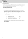
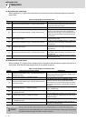
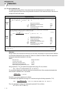
7-1-4 Expressions for load inertia calculation
The calculation method for a representative load inertia is shown.
Type Mechanism Calculation expression
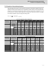
Cylinder
T
L
:Load inertia(kg•cm
2
)
ρ: Density of cylinder material(kg/cm
3
)
L:Length of cylinder(cm)
D
1
:Outer diameter of cylinder(cm)
D
2
:Inner diameter of cylinder(cm)
W:Mass of cylinder(kg)
<Reference data(Material densities)>
Iron:7.80×10
-3
(kg/cm
3
) Aluminum:2.70×10
-3
(kg/cm
3
)
Copper:8.96×10
-3
(kg/cm
3
)
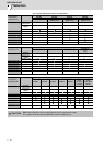
J
L
:Load inertia(kg•cm
2
)
W:Mass of cylinder(kg)
D:Outer diameter of cylinder(cm)
R:Distance between rotary axis and cylinder axis(cm)
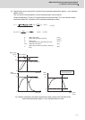
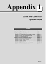
Column
J
L
: Load inertia(kg•cm
2
)
W:Mass of cylinder(kg)
a,b,R:Left diagram(cm)
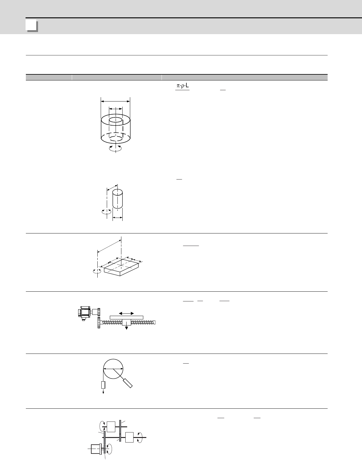
Object that moves
linearly
J
L
:Load inertia(kg•cm
2
)
W:Mass of object that moves linearly(kg)
N:Motor speed(r/min)
V:Speed of object that moves linearly(mm/min)
ΔS:Object movement amount per motor rotation(mm)
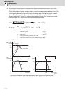
Suspended object
J
L
:Load inertia(kg•cm
2
)
W:Object mass(kg)
D:Diameter of pulley(cm)
Jp:Inertia of pulley(kg•cm
2
)
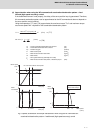
Converted load
J
L
:Load inertia(kg•cm
2
)
J
A
,J
B
:Inertia of load A, B(kg•cm
2
)
J
11
~J
31
:Inertia(kg•cm
2
)
N
1
~N
3
:Each shaft’s speed(r/min)
ǾD
1.
ǾD
2.
Rotary shaft is cylinder center
Rotary shaft
J
L
=
.
(D
1
4
-D2
4
) =
.
(D1
2
D2
2
)
9
R
D
When rotary shaft and cylinder
shaft are deviated
Rotary shaft
J
L
=
.
(D
2
+8R
2
)
8
W
R
a
a
b
b
Rotary shaft
JL = W(
+R
2
)
a
2
+b
2
W
V
N
Servo
motor
J
L
= W(
.
)
2
= W( )
2
10
1
V
ΔS
2πN
20π
D
W
J
L
= W(
)
2
+J
p
D
2
N
2
J
A
J
B
N
3
J
31
N
1
N
1
J
11
J
22
J
21
Load A
Servo
motor
Load B
J
L
= J
11
+(J
21
+J
22
+J
A
)
.
(
)
2
+
(J
+J
B
)
.
(
)
2
N1
N2
N1
N3