


-36-
For Machines Mfg. Since 7/09
Model SB1016/SB1036
OPERATION
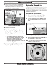
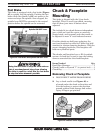
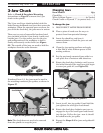
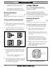
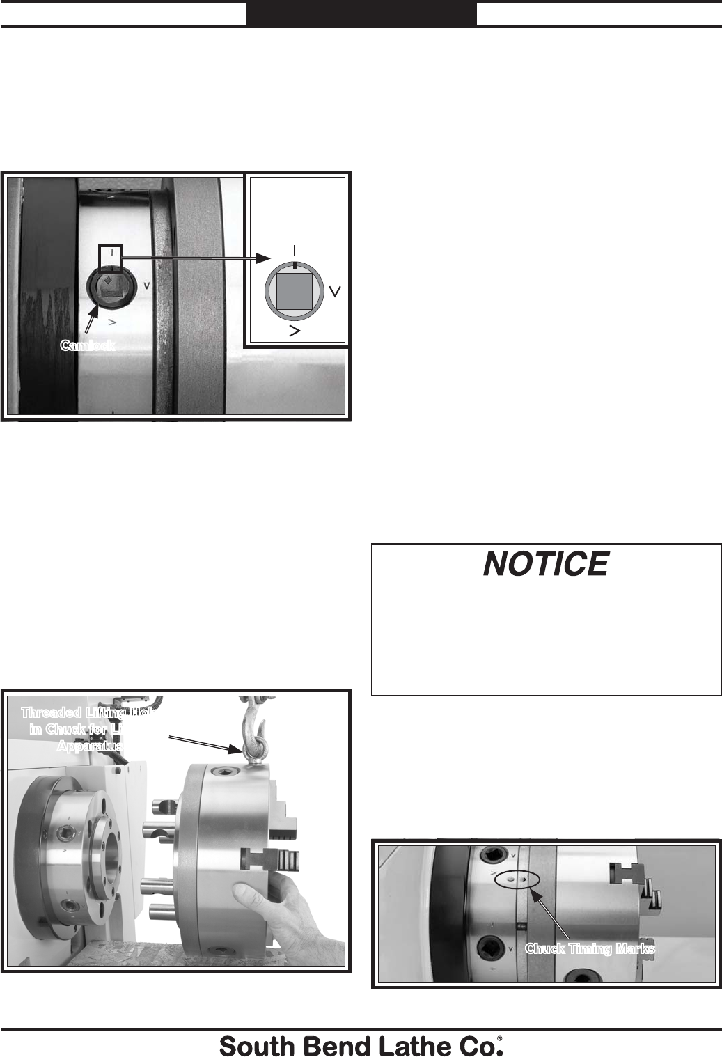
3. One at a time, use the chuck key to turn
each of the camlocks counterclockwise until
the cam line aligns with the cam release
datum line, as shown in Figure 47. As you
turn the camlocks, they will rise up slightly
from the spindle body.
Figure 47. Camlock loosened with the cam line aligned
with the datum line.
4. Remove the chuck key, then use a dead-
blow hammer or a wood block to lightly tap
around the circumference of the chuck or
faceplate to break it free from the spindle
taper and camlock sockets. Be sure to
support the bottom of the chuck.
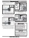
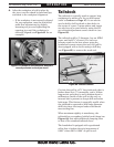
5. With a rocking motion, carefully remove the
chuck or faceplate from the spindle nose, as
shown in Figure 48, making sure to support
the weight with an adequate chuck cradle.
Figure 48. Removing the 3-jaw chuck from a spindle
nose.
Threaded Lifting Hole
in Chuck for Lifting
Apparatus
Camlock
Cam Release
Datum Line
and Cam Line
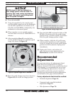
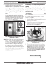
Mounting Chuck or Faceplate
The 4-jaw chuck is shipped with six camlock
studs that may have to be installed before
chuck mounting. If you have not yet installed
the camlock studs, complete the instructions in
"Installing and Adjusting Camlock Studs" on
Page 37.
To mount a chuck or faceplate:
1. DISCONNECT LATHE FROM POWER!
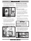
2. Lay a chuck cradle (see Figure 46) or
plywood under the chuck or faceplate and
over the bedway to protect the precision
ground surfaces from damage and reduce
injury if fingers get pinched.
3. Clean away debris and oily substances from
the mating surfaces of the spindle and chuck
or faceplate.
4. Inspect and make sure that all camlock
studs are undamaged, are clean and lightly
oiled, and that the camlock stud cap screws
are in place and snug.
Never install a chuck or faceplate without
having the camlock cap screws in place or
fully tightened. If you ignore this notice,
the chuck may not be removable since the
camlock studs may turn with the camlocks
and never release.
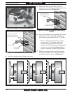
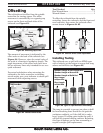
5. Position the chuck/faceplate in front of the
spindle nose, align the chuck timing marks,
as shown in Figure 49, and align the cam-
lock studs with the sockets, then carefully
insert the chuck or faceplate onto the
spindle.
Figure 49. Chuck timing marks aligned.
Chuck Timing Marks