


For Machines Mfg. Since 7/09 Model SB1016/SB1036
-83-
SERVICE
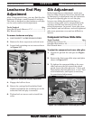
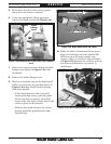
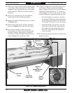
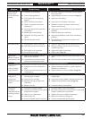
Motor Kill Limit Switch
Plunger and Cam Lobe
Figure 149. Brake pedal motor kill switch.
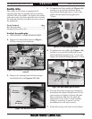
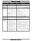
10. While the lathe is disconnected from power
have your assistant move the spindle ON/
OFF lever up to forward, neutral, and
reverse, while you verify the lobe rod shown
in Figure 150 operates the switches without
any loose switch mounts, cap screws, or
interference.
Figure 150. Lobe rod and spindle ON/OFF switch.
Lobe Rod
Spindle
ON/OFF
Switches
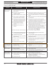
5. Place sheet of wood on the ways to protect
them when the chuck is removed.
6. Using the appropriate lifting apparatus,
remove the chuck as shown in Figure 148.
Figure 148. Removing the 3-jaw chuck from a spindle
nose.
Brake
Linkage
Cover
7. Remove the cap screws that fasten the brake
linkage cover shown in Figure 149 to the
headstock.
8. Remove the brake linkage cover.
9. Have your assistant step on the brake pedal
while you verify that the cam lobe shown in
Figure 149 makes the kill switch plunger
click when pushed.
— If the switch does not click, loosen the
switch mounting screws, push the pedal
all the way down, and move the switch
closer to the lobe until it clicks. Secure the
switch in place at this location.
— With the foot pedal released, the switch
plunger should be approximately 3mm
from the lobe.