


For Machines Mfg. Since 7/09 Model SB1016/SB1036
-79-
SERVICE
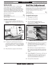
Saddle Gibs
The saddle on this lathe is equipped with
opposing gibs that lie parallel with one another
on either side of the saddle. To tighten the saddle
and remove play, the front gib must move toward
the tailstock, and the rear gib must move toward
the headstock.
Tools Needed: Qty
Hex Wrench 6mm .................................................1
Standard Screwdriver #3 ......................................1
To adjust the saddle gibs:
1. DISCONNECT LATHE FROM POWER!
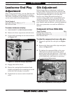
2. Remove the thread dial shown in Figure
137 by removing the lock knob.
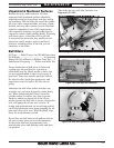
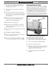
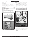
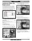
Figure 139. Location of carriage lock and half nut for
removal.
Carriage
Lock Block
3. Remove the carriage lock and the carriage
lock-block shown in Figures 137–140.
Carriage
Lock
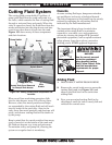
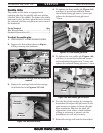
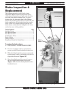
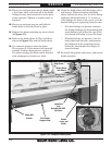
4. To tighten the front saddle gib (Figure 141)
and move it toward the tailstock, loosen
the tailstock-facing gib screw
1
⁄4-turn, and
tighten the headstock-facing gib screw
1
⁄4-turn.
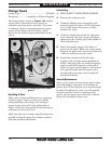
Thread
Dial
Knob
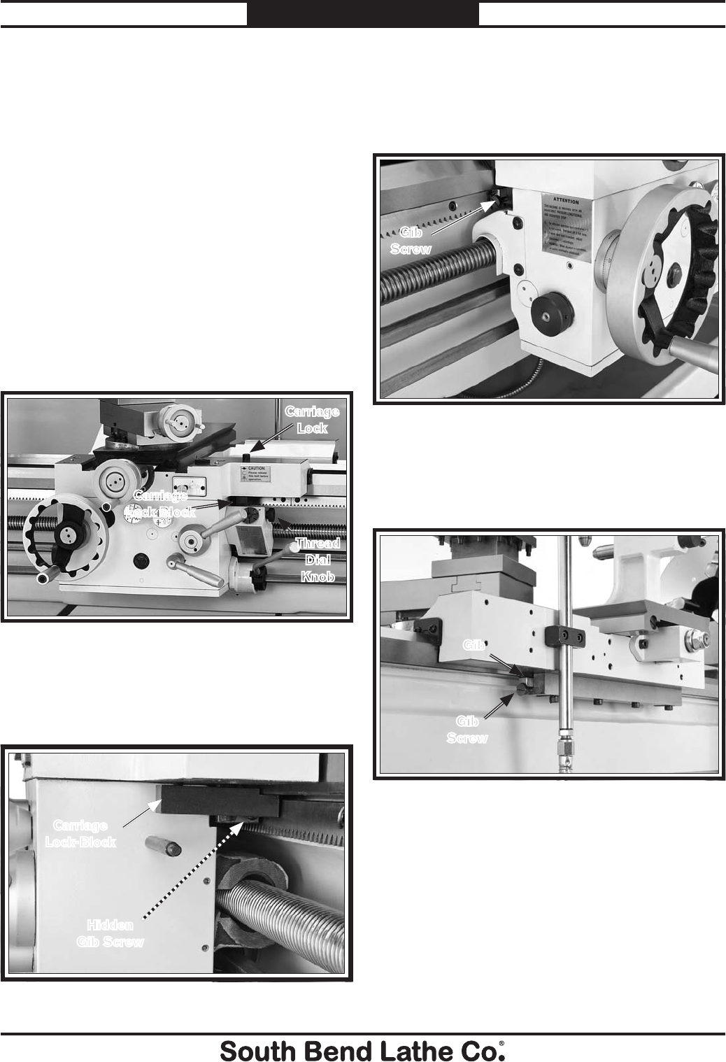
Hidden
Gib Screw
Figure 140. Gib screw access.
Figure 141. Front saddle gib screw.
Gib
Screw
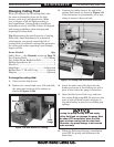
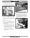
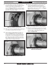
5. To tighten the rear saddle gib (Figure 142)
and move it toward the headstock, loosen
the headstock-facing gib screw
1
⁄4-turn, and
tighten the tailstock-facing gib screw
1
⁄4-turn.
Figure 142. Rear saddle gib and screw.
Gib
Screw
Gib
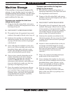
6. Test the feel of the carriage by turning the
handwheel. Re-adjust the gib screws in the
same manner to tighten or loosen the gibs.
Most machinists find that the ideal gib
adjustment is one where a small amount
of drag or resistance is present yet the
handwheels are still easy to move.
7. Reinstall carriage lock and the thread dial.
Carriage
Lock-Block