


-52-
For Machines Mfg. Since 7/09
Model SB1016/SB1036
OPERATION
Manual Feed
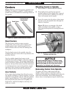
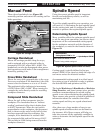
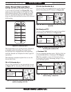
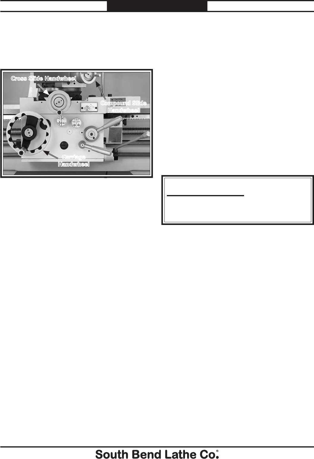
These three handwheels (see Figure 83)
manually position and control the cutting tool for
lathe operations.
Carriage Handwheel
Moves the carriage parallel along the ways,
and is equipped with a graduated collar in
increments of 0.010" where 360°= 0.990". The
handwheel can also be disengaged when power
feed operations would make it an entanglement
hazard by pushing it in.
Cross Slide Handwheel
Moves the cross slide perpendicular to the ways.
For every revolution of the handwheel, the slide
moves twice the distance or at a at a 1:2 ratio.
The graduated collar indicates in increments
of 0.001"where 360°= 0.200". When turning for
example the scale directly reads the resulting
workpiece diameter.
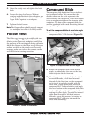
Compound Slide Handwheel
Moves the tool in fine increments into the
workpiece. The handwheel has an "indirect
reading" graduated collar that is broke down
in 0.001" increments. When the tool path is
perpendicular to the workpiece, the movement
that is shown on the scale is only half of what
has been removed from the workpiece. For
example, if the handwheel is rotated 0.001"
the compound slide and tool bit moves 0.001".
This results in 0.002: being removed from the
workpiece diameter.
Figure 83. Carriage handwheels.
Cross Slide Handwheel
Compound Slide
Handwheel
Carriage
Handwheel
Spindle Speed
Using the correct spindle speed is important
for safe and satisfactory results, as well as
maximizing tool life.
To set the spindle speed for your operation, you
will need to: (1) Determine the best spindle speed
for the cutting task, and (2) configure the lathe
controls to produce the required spindle speed.
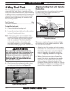
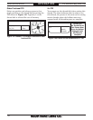
Determining Spindle Speed
Many variables affect the optimum spindle speed
to use for any given operations, but the two most
important are the recommended cutting speed
for the workpiece material and the diameter of
the workpiece, as noted in the formula shown in
Figure 84:
Cutting speed, typically defined in feet per
minute (FPM), is the speed at which the edge of a
tool moves across the material surface.
A recommended cutting speed is an ideal speed
for cutting a type of material in order to produce
the desired finish and optimize tool life.
The books Machinery’s Handbook or Machine
Shop Practice, and some internet sites, provide
excellent recommendations for which cutting
speeds to use when calculating the spindle speed.
These sources also provide a wealth of additional
information about the variables that affect
cutting speed and they are a good educational
resource.
Also, there are a large number of easy-to-use
spindle speed calculators that can be found on
the internet. All of these sources will help you
take into account all the applicable variables in
order to determine the best spindle speed for the
operation.
Cutting Speed (FPM) x 12
*Recommended
Dia. of Cut (in inches) x 3.14
= SpindleSpeed (RPM)
*Double if using carbide cutting tool
Figure 84. Spindle speed formula for lathes.