


-48-
For Machines Mfg. Since 7/09
Model SB1016/SB1036
OPERATION
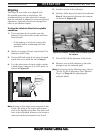
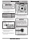
Mounting Center in Tailstock
Either the carbide-tipped dead center or a live
center can be mounted in the tailstock. Mounting
instructions are the same for both.
To mount a center in the tailstock:
1. DISCONNECT LATHE FROM POWER!
2. Thoroughly clean and dry the tapered
mating surfaces of the tailstock quill bore
and the carbide-tipped dead center, making
sure that no lint or oil remains on the tapers.
3. Use the tailstock quill handwheel to feed the
quill out from the casting about 1". (Do not
feed the quill out of the casting more than 2"
or stability and accuracy will be reduced.)
4. Insert the center into the tailstock quill.
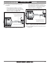
5. Seat the center firmly into the quill during
workpiece installation by rotating the quill
handwheel clockwise to apply pressure, with
the center engaged in the center hole in the
workpiece.
Note: Only apply enough pressure with the
tailstock quill to securely mount the
workpiece between centers. Avoid over-
tightening the center against the workpiece,
or it may become difficult to remove later,
and it will result in excessive friction and
heat, which may damage the workpiece and
the center.
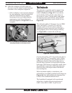
Removing Center from Tailstock
To remove the center from the quill, hold onto it
with a rag in one hand, then rotate the tailstock
handwheel counterclockwise to draw the quill
back into the casting until the center releases.
If the center does not come out, extend the quill,
and use a drift key (see Figure 62) to drive the
center out.
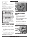
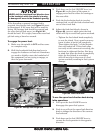
The steady rest supports long shafts from
3
⁄4" to
8
3
⁄4" in diameter and can be mounted anywhere
along the length of the bed.
To install and use the steady rest:
1. DISCONNECT LATHE FROM POWER!
2. Thoroughly clean all mating surfaces, then
place the steady rest base on the bedways
so the triangular notch fits over the bedway
prism.
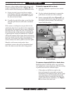
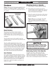
3. Position the steady rest where required to
properly support the workpiece, then tighten
the hex nut shown in Figure 76.
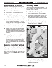
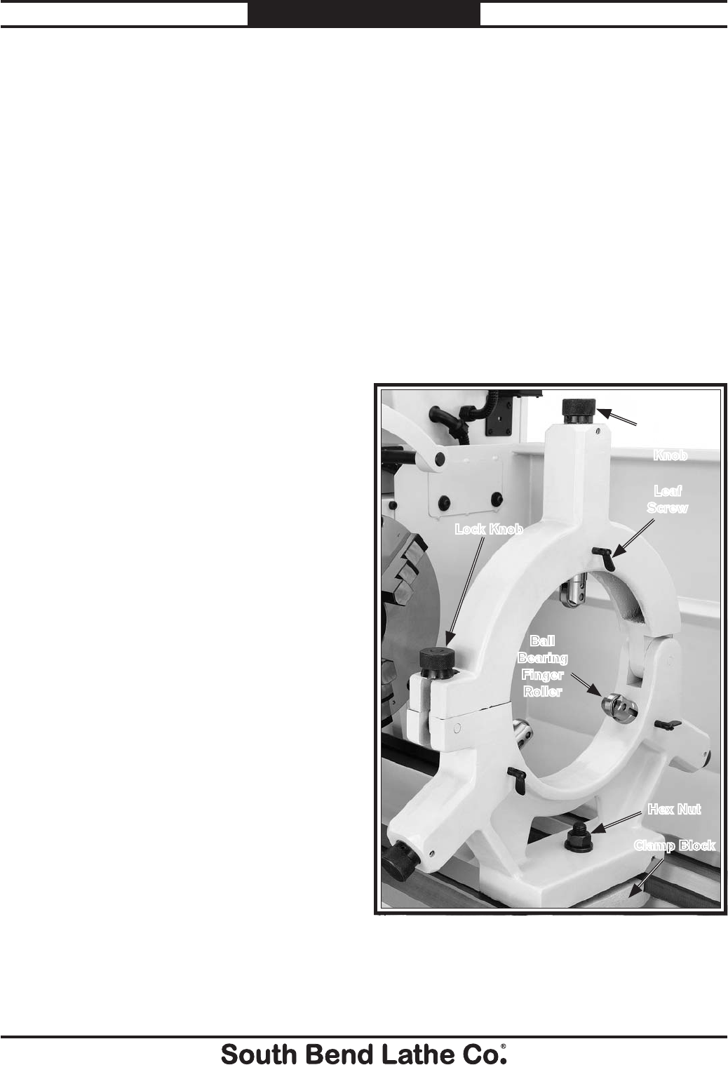
Steady Rest
4. Loosen the lock knob (Figure 76), open the
steady rest, and install the workpiece so it is
supported at both ends.
Figure 76. Steady rest components.
Lock Knob
Hex Nut
Finger
Adjustment
Knob
Ball
Bearing
Finger
Roller
Leaf
Screw
Clamp Block