


For Machines Mfg. Since 7/09 Model SB1016/SB1036
-59-
OPERATION
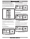
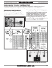
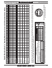
Understanding Thread & Feed Rate Chart
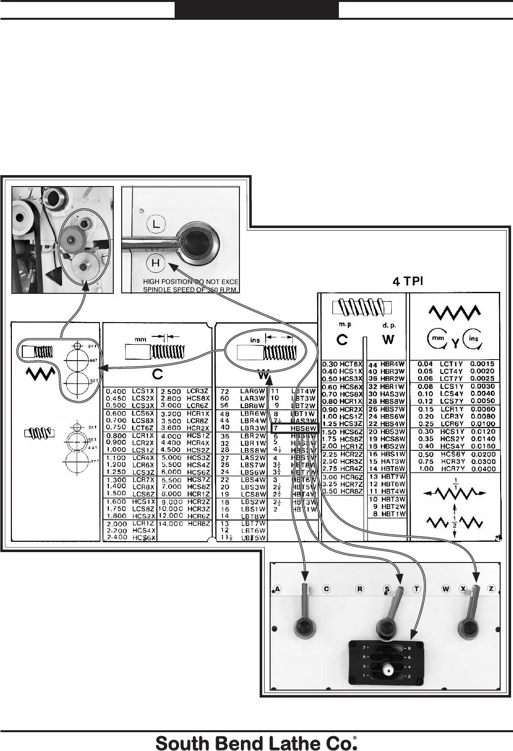
A complete threading and feed rate chart is located on the face of the headstock that shows all
available threading and feed configurations for your lathe. Chart use is described below.
Figure 103. Using feed chart with lathe controls.
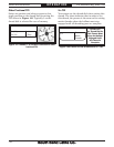
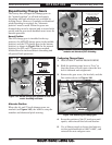
Positioning Gearbox Levers
To cut a thread or establish a particular feed
rate, you may need to first reposition the
transposing gears located behind the end gear
cover.
Once you have confirmed that the change gears
are positioned according to what the thread and
feed rate charts require, you then can move the
quick change gearbox levers to the required
positions, which are indicated by an alpha-
numeric code on the thread and feed rate chart.
For this example, an inch thread of 7 TPI is
desired. The alpha-numeric code displayed on the
chart shown in Figure 103 is HBS8W.